1 Supplementary Operating Manual
8 of 48
AmaControl
2301.83/04-EN
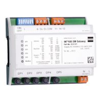
1.3.4 Setting stop bits and parity
Stop bits / parity
Fig.3: Setting stop bits and parity via DIP switches 5 and 6
Table9: Selection of stop bits / parity
DIP switch 5 DIP switch 6 Address
OFF OFF 1 / even
ON OFF 1 / odd
OFF ON 2 / no (factory setting)
ON ON 1 / no
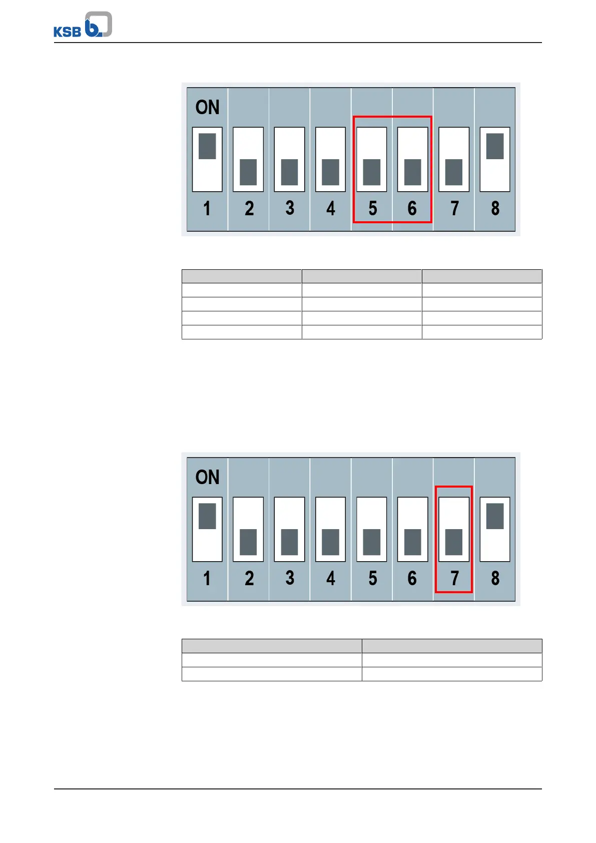
1.3.5 Monitoring the DP ports
DP port monitoring After connecting and parameterising the Modbus communication, the settings can
be saved by means of DIP switch7. If a failure of the AmaControl devices connected
to the DP ports is registered, the error status (1= error) is displayed in the "dec9734
(FC4)" register of the INT 600 DM Gateway. Alerts are issued with a delay of about
2minutes. Parallel to this message the respective seconds counters of the individual
AmaControl devices can be read out (FC4) for an additional evaluation (e.g.used as a
sign of life) (ðSection1.4.5,Page40) .
Fig.4: Activating DP port monitoring via DIP switch 7
Table10: DP port monitoring
DIP switch 7 Address
ON Activated
OFF Deactivated
 Loading...