2361:124 2361:121
2542:22
2361:123
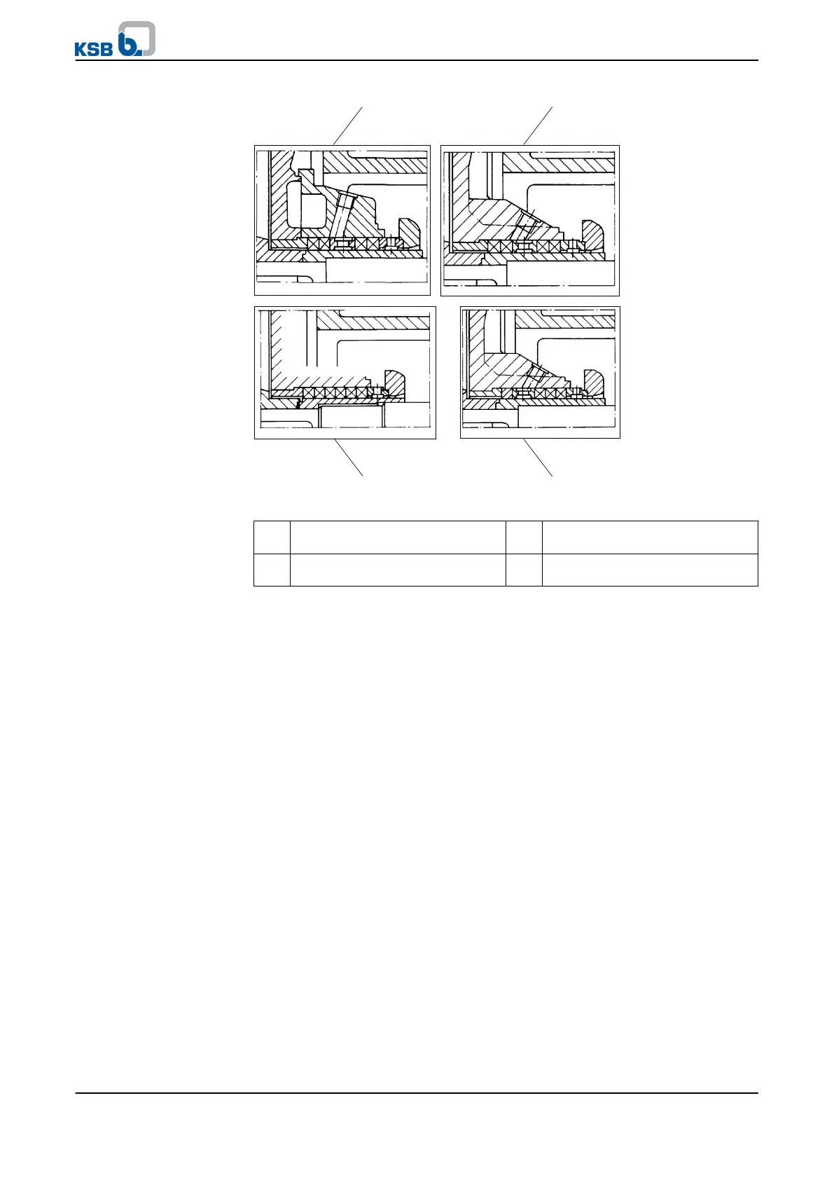
1 2
3
4
Fig. 21: Available models
1/2 Packing with barrier liquid
connection (standard)
3 Packing without lantern ring
4 Packing with flushing liquid
connection
For pure graphite packings see supplementary operating instructions.
Always use pre-compressed packing rings.
✓ The assembled bearings as well as the individual parts are kept in a clean and
level assembly area.
✓ All disassembled parts have been cleaned and checked for wear.
✓ Any damaged or worn parts have been replaced by original spare parts.
✓ The sealing surfaces have been cleaned.
✓ The notes and steps stated in (⇨ Section 7.5.1 Page 54) to (⇨ Section 7.5.3 Page
55) have been observed/carried out.
1.
Screw stuffing box housing 451.01 (if any) to discharge cover 163.
Tightening torque (⇨ Section 7.6.1 Page 64)
2. Press neck bush 456.01 into the discharge cover.
3. For packings with barrier liquid connection (see illustration "Available models",
items 1 and 2) also fit lantern ring 458.01 in its specified location.
4. Insert the first packing ring, ensuring that its cut edge is in horizontal position.
5. Hold the packing ring in place and slide shaft protecting sleeve 524 (chamfered
side first) into the gland packing chamber from the pump end.
6. Slightly expand the inside diameter of the packing ring by moving the shaft
protecting sleeve back and forth. Then pull out shaft protecting sleeve 524.
Insert each subsequent packing ring separately with its cut edge offset by 90° in
relation to the previous one. Repeat the expansion procedure.
Insert lantern ring 458.01, if any, in its the specified location (see illustration
"Available models").
After inserting the last packing ring, shaft protecting sleeve 524 remains in the
packing chamber.
Models
Procedure
7 Servicing/Maintenance
KWP
59 of 78