▪ Delivery address
▪ Mode of dispatch (freight, mail, express freight, air freight)
Refer to the exploded view or general assembly drawing for part numbers and
descriptions.
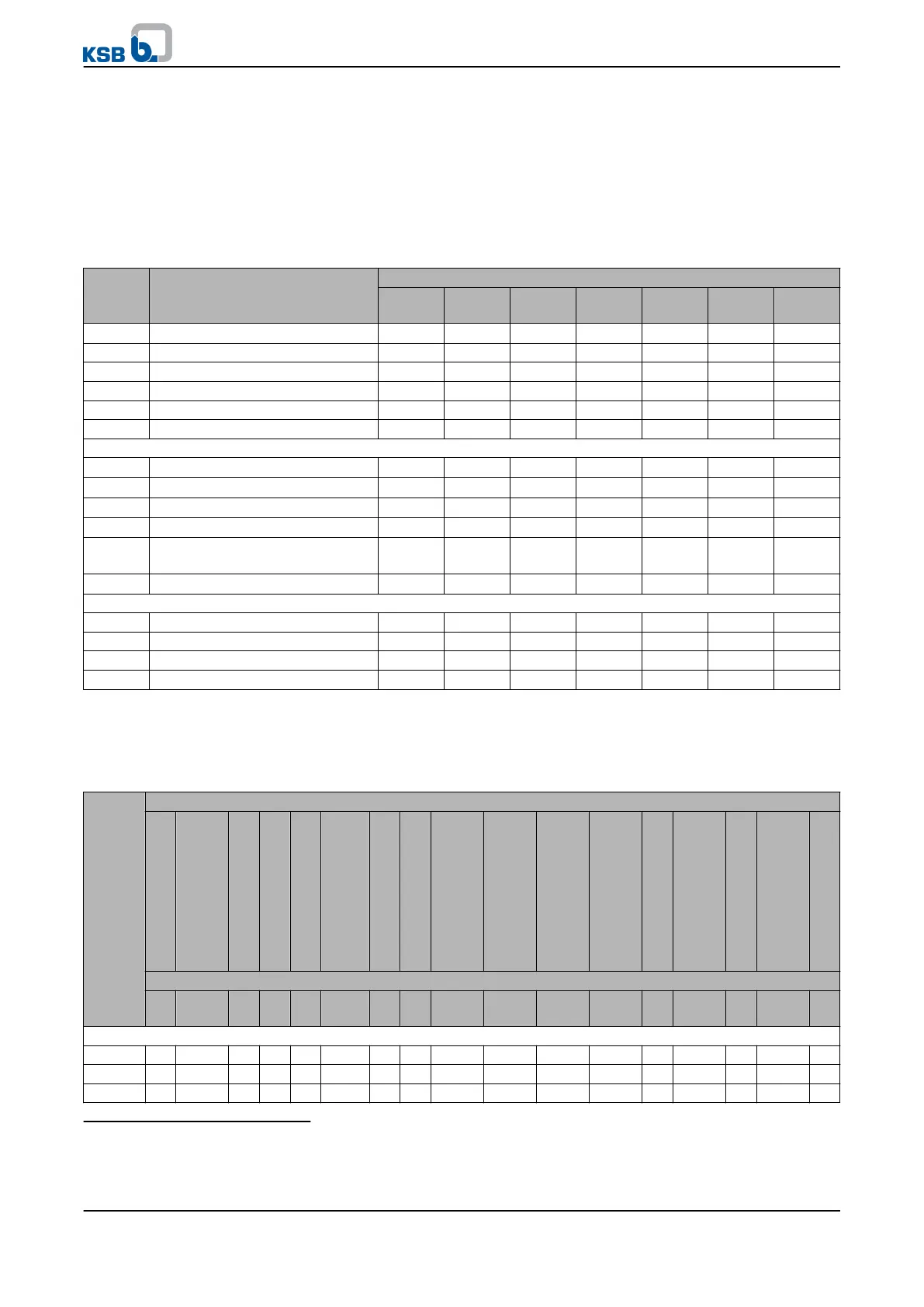
7.7.2 Recommended spare parts stock for 2 years' operation to DIN 24296
Table 25: Quantity of spare parts for recommended spare parts stock
Part No. Description Number of pumps (including stand-by pumps)
2 3 4 5 6 and 7 8 and 9 10 and
more
135.01
Wear plate
20)
2 2 2 3 3 4 50%
210 Shaft 1 1 1 2 2 2 20%
230 Impeller 1 1 1 2 2 2 20%
320.02 Angular contact ball bearing (set) 1 1 2 2 2 3 25%
322.01 Cylindrical roller bearing 1 1 2 2 2 3 25%
330 Bearing bracket, complete - - - - - 1 2
Models with mechanical seal
433.01
Mechanical seal, complete
21)
1 1 2 2 2 3 25%
Spring-loaded ring
21)
2 3 4 5 6 7 90%
Seat ring
21)
2 3 4 5 6 7 90%
Secondary seal at seat ring
21)
2 3 4 5 7 9 100%
Secondary seal at spring-loaded
ring
21)
2 3 4 5 7 9 100%
Spring (set)
21)
1 1 1 1 2 2 20%
Pump with gland packing
456.01 Neck bush 1 1 2 2 2 3 30%
461.01 Gland packing (set) 4 4 6 6 6 8 100%
524.01 Shaft protecting sleeve 2 2 2 3 3 4 50%
--- Gaskets for pump casing (set) 4 6 8 8 9 12 150%
7.7.3 Interchangeability of pump components
Components featuring the same number in a column are interchangeable.
Table 26: Interchangeability of pump components
Pump size
Description
Pump casing
Suction wear plate
Discharge cover
Shaft
Impeller
Rolling element bearing
Bearing bracket
Bearing bracket lantern
Stuffing box housing
Gland follower
Stuffing box ring
Lantern ring
Gland packing
Casing wear ring
Thrower
Shaft protecting sleeve
Impeller screw
Part No.
101 135.01 163 210 230 320/
322
330 344 451.01 452.01 454.01 458.01 461 502.01 507 524.01 906
Bearing bracket P03ax
40-250 1 1 1 1 1 1 1 1 1 1 1 1 1 - 1 1 1
50-200 2 2 2 1 2 1 1 2 1 1 1 1 1 - 1 1 1
50-201 2 2 2 1 33 1 1 2 1 1 1 1 1 - 1 1 1
20)
For KWP 250-315, 300-400 and 350-400: wear plate is replaced by casing wear ring
21)
Optional
7 Servicing/Maintenance
KWP
65 of 78