5 Installation at site
17 of 34
KSB Leakage Sensor
1984.8/02-EN
5.4 Electrical connection
CAUTION
Improper electrical connections
Damage to the device!
▷ Check the electrical connection.
▷ Observe the wiring diagrams.
5.4.1 Standard design
The KSB Leakage Sensor is supplied with two pre-configured cables of 10m length
each.
▪ The power cable (connection EXT) is supplied with an open cable end.
▪ The sensor cable is supplied with two M12 connectors.
Optionally, a third cable is supplied for transmitting the leakage rate to an external
analysis device. (10m length, 4-core, open cable end and M12 connector, KSB
material number 05059190)
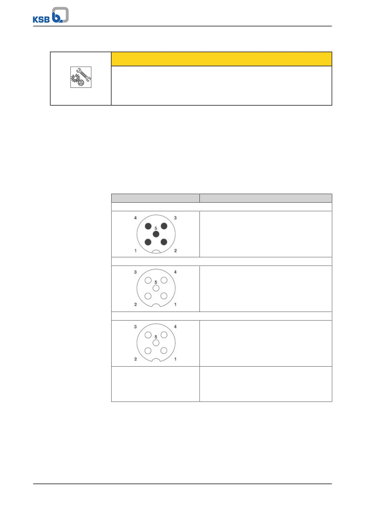
Table6: Pin assignment of the display unit
Illustration Power supply and signals to external device
M12 connector EXT
1: Power supply 24VDC (+V
B-IN
)
2: Signal 1 red (open collector signal)
3: GND (-V
B-IN
)
4: Signal 2 yellow (open collector signal)
5: Signal 3 green (open collector signal)
M12 socket IN1
1: Power supply 24VDC (+V
B-OUT
)
2: Signal sensor
3: GND(-V
B-OUT
)
4: (not connected)
5: (not connected)
M12 socket IN2
1: OUT 4-20 mA (+) leakage rate
2: (not connected)
3: OUT 4-20mA (-) leakage rate
4: (not connected)
5: (not connected)
Colour coding of the power
cable cores
1: BN = brown
2: WH = white
3: BU = blue
4: BK = black
5: GY = grey