5 Installation at site
19 of 34
KSB Leakage Sensor
1984.8/02-EN
3 M12 socket IN2
4 M12 connector EXT
▪ The analysing unit is connected via a 5-pin M12 plug-type connection for the
power supply and message signals.
– Use the M12 connector EXT.
▪ The leakage sensor is connected via a 3-pin M12 plug-type connection.
– Use the M12 socket IN1.
▪ The optional analog output signal “leakage rate” can be connected via a 3-pin
M12 plug-type connection.
– Use the M12 socket IN2.
1. Precisely align the M12 plug-type connections and completely screw them into
the analysing unit.
2. Tighten the screwed connections hand-tight. Observe a tightening torque of
0.4-0.6Nm.
3. Fasten the analysing unit to a level surface with an M5 screw, screw length =
8mm. Observe a tightening torque ≤ 2Nm.
5.4.4 DIP switch configuration
NOTE
Behind the service interface a leakage rate for analysis can be configured using the
four micro switches. After this configuration, securely close the access with the
screw plug. Enclosure IP65 only applies when the service interface is closed and the
sensors are connected correctly.
NOTE
The setting of the DIP switches must only be adjusted after the analysing unit has
been de-energised.
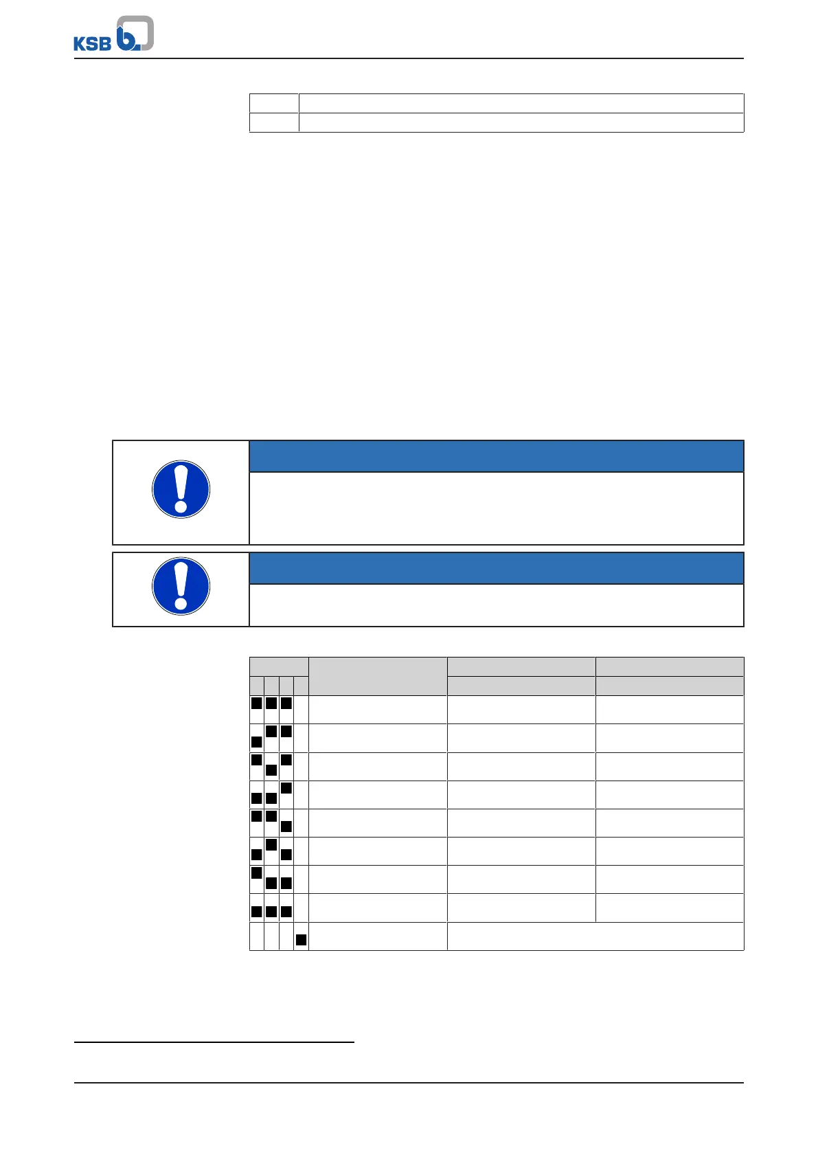
Table8: Setting 8 fixed warning levels and alarm levels using the DIP switches:
ON_ECE Level Warning threshold Alarm threshold
1 2 3 4 g/h g/h
X 1 0,1 2
X 2 0,2 3
X 3 0,3 3
X 4
4)
0,3 5
X 5 0,3 8
X 6 0,5 8
X 7 1 12
X 8 2 30
X X X Mute Acoustic signal deactivated
4
Factory setting