9 Related Documents
30 of 34
KSB Leakage Sensor
1984.8/02-EN
9.2.2 Variant for use in potentially explosive atmospheres
UG1839893_ZDK_D02_001/03
1
2
3
4
5
6
7
8
14
10
11
A
B
12
13
9
8E
8B
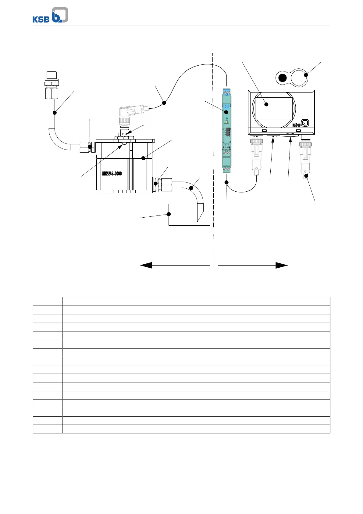
Fig.8: Connection diagram of the KSB Leakage Sensor (variant for use in potentially explosive atmospheres)
A = potentially explosive atmosphere
B = non-potentially explosive atmosphere
1 Leakage line from the pump
2 Indicator lamp, orange
3 Blue sensor cable
4 Analysing unit
5 Magnetic clip (for resetting the analysing unit)
6 Power cable
7 Screw plug (access to the DIP switches)
8 Connection for analog output signal (leakage rate)
9 Site-supplied leakage collector
10 Leakage line from the sensor housing
11 Leakage sensor
12 Vent opening
13 Switching amplifier
14 Black sensor cable
8B Leakage drain
8E Leakage inlet