9 Related Documents
29 of 34
KSB Leakage Sensor
1984.8/02-EN
9.2 Layout / connection diagram
9.2.1 Standard design
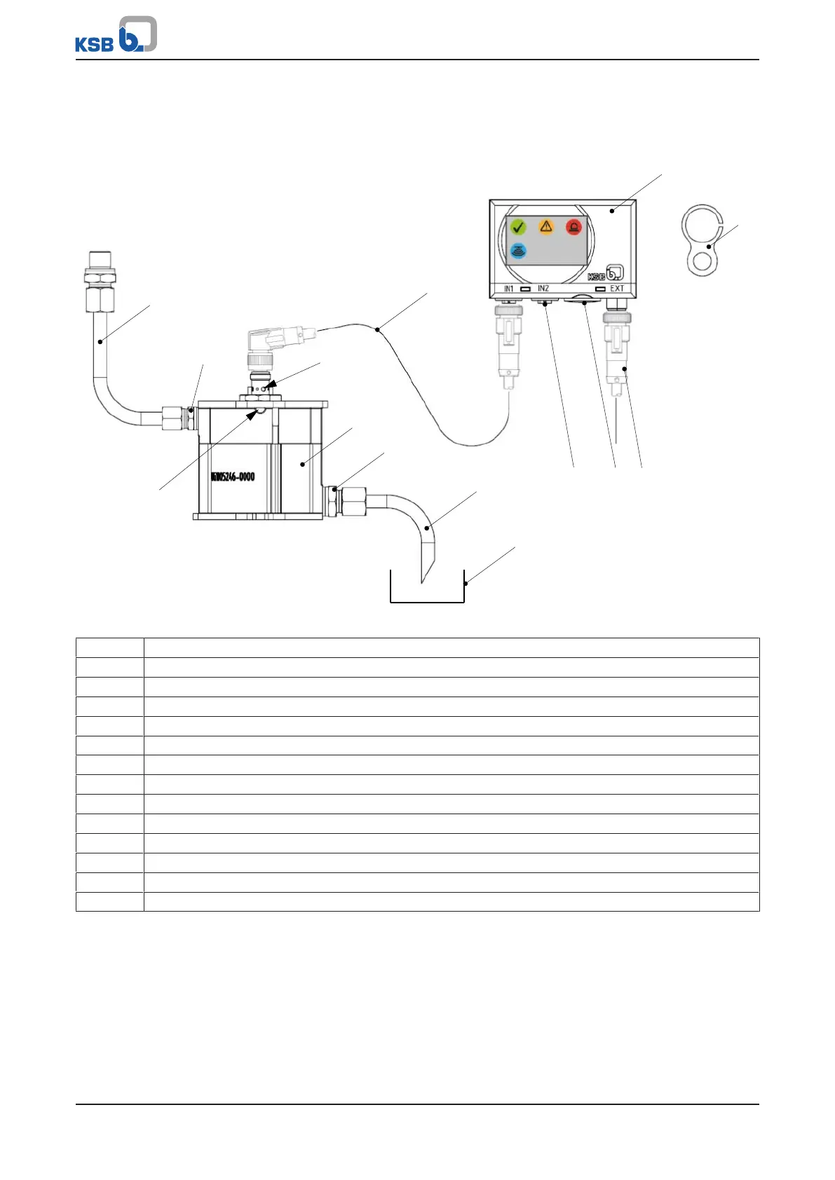
Fig.7: Connection diagram of the KSB Leakage Sensor (standard design)
1 Leakage line from the pump
2 Indicator lamp, orange
3 Sensor cable
4 Analysing unit
5 Magnetic clip (for resetting the analysing unit)
6 Power cable
7 Screw plug (access to the DIP switches)
8 Connection for analog output signal (leakage rate)
9 Site-supplied leakage collector
10 Leakage line from the sensor housing
11 Leakage sensor
12 Vent opening
8B Leakage drain
8E Leakage inlet