7 Servicing/Maintenance
25 of 34
KSB Leakage Sensor
1984.8/02-EN
7.3 Dismantling and reassembly
7.3.1 Dismantling and reassembling the KSB Leakage Sensor
ü All power cables as well as the electrical devices connected to them have been
de-energised.
1. Disconnect the M12 connector from connection EXT at the analysing unit.
2. Disconnect the sensor cable IN1 and the cable for analog signal IN2 from the
analysing unit.
3. Remove the KSB Leakage Sensor from the pump set.
4. Fit the KSB Leakage Sensor again in the required position.
5. Re-connect the sensor cable IN1 and the cable for analog signal IN2 to the
analysing unit.
6. Re-connect the M12 connector EXT to the analysing unit.
ð The KSB Leakage Sensor is now connected.
7. Return the KSB Leakage Sensor to service.
7.3.2 Rotating the upper half of the sensor housing
If the leakage inlet 8E is to be positioned on the same side as the leakage drain 8B,
the upper half of the sensor housing can be taken off, rotated by 180° and mounted
in this position.
ü All power cables as well as the electrical devices connected to them have been
de-energised.
1. Undo the hexagon socket head cap screws 914.2 at the upper housing half
105.01.
2. Remove the upper housing half, turn it by 180°, and mount it in this position.
3. Screw in hexagon socket head cap screws 914.2 and tighten them hand-tight.
4. Carry out a functional test. (ðSection6.1,Page22)
7.3.3 Removing and re-mounting the inductive sensor
Inductive sensor 69-8 is supplied fitted in the upper housing half with the required
distance to indicator 620 (balance scale). The position of the measurement
transmitter must not be changed by turning it.
If it has been turned or if the measurement transmitter is to be replaced, carry out
the following steps to position it correctly:
1. Undo hexagon socket head cap screws 914.2 at the upper housing half 105.01.
2. Remove the upper housing half 105.01.
3. Undo the locknut of inductive sensor 69-8.
4. Unscrew inductive sensor 69-8 from the upper housing half 105.01.
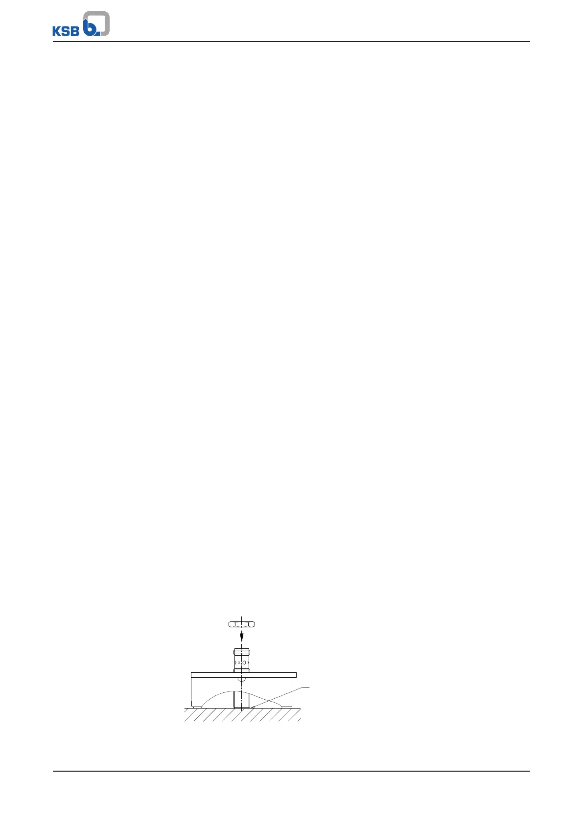
5. Place the upper housing half in a level work area with measuring instrument
690 (bullseye level) on top. Fasten it with suitable clamping equipment.
Fig.4: Mounting the inductive sensor