5 Installation at site
20 of 34
KSB Leakage Sensor
1984.8/02-EN
5.5 Display functions during operation
5.5.1 Display
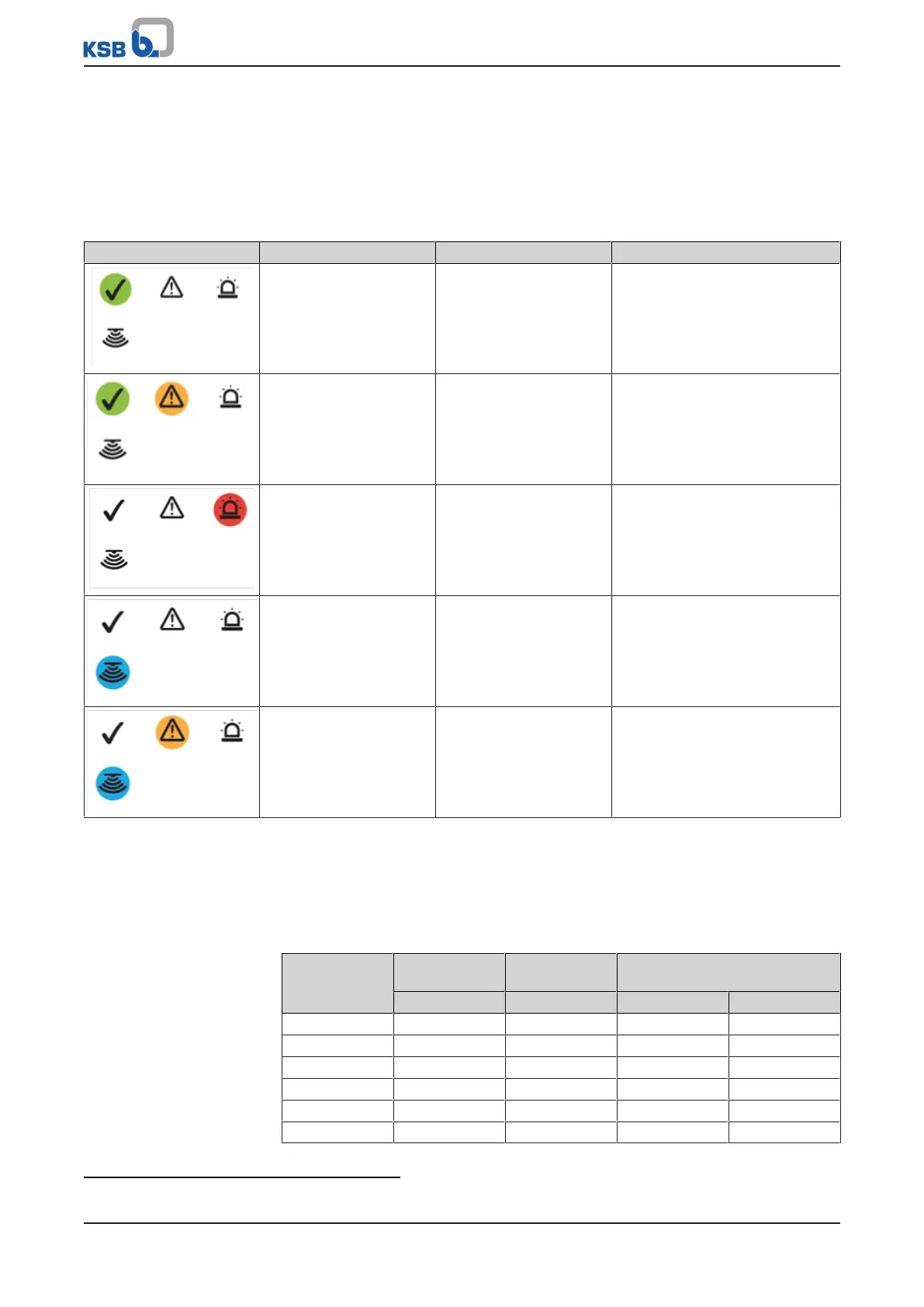
The display of the analysing unit indicates the status of the leakage sensor with light
signals (LEDs).
Table9: Overview of light signals and open collector signals
Display Light signal (LED) Open collector signal Description
GREEN lit continuously Signal 3, green,
connected
Ready for operation, leakage
monitoring active
GREEN lit continuously
YELLOW lit continuously
Signal 3, green,
connected
Signal 2, yellow,
connected
Warning, set warning threshold
exceeded
RED lit continuously
Acoustic warning
Signal 1, red, connected Alarm, set alarm threshold
exceeded
BLUE lit for 1second - Inductive sensor triggered
BLUE lit continuously
YELLOW flashing
Signal 2, yellow, flashing
frequency applied
Warning, contact to inductive
sensor interrupted
or balance scale jammed/ in
incorrect position
5.5.2 Analog output
The analog output supplies a 4-20mA signal, indicating the averaged leakage rate
depending on the sensitivity level set via the DIP switches (ðSection5.4.4,Page19)
as per the following table.
Table10: Calculation factors
Level Leakage rate at
4mA
Leakage rate at
20mA
Calculation factors
[g/h] [g/h] A B
1 ≤ 0,02 ≥ 4 269730 13432,5
2 ≤ 0,04 ≥ 6 134820 6705
3 ≤ 0,06 ≥ 6 89820 4455
4
5)
≤ 0,06 ≥ 10 89892 4473
5 ≤ 0,06 ≥ 16 89932,5 4483,125
6 ≤ 0,1 ≥ 16 53932,5 2683,125
5
Factory setting