7 Servicing/Maintenance
26 of 34
KSB Leakage Sensor
1984.8/02-EN
6. Screw inductive sensor 69-8 in from the top (2), until it touches the work area
(1).
7. The lower edge of upper housing half 105.01 and the active face of inductive
sensor 69-8 are now on the same level.
NOTE
The lengths of the inductive sensors in the standard design differ from those of the
variant for use in potentially explosive atmospheres. For this reason, the sensors
protrude from the upper housing half at different lengths.
8. Screw the locknut on from the top and tighten it. The inductive sensor must not
be turned during this process.
9. Place upper housing half 105.01 on lower housing half 105.02. Observe the
position of leakage inlet 8B in relation to leakage drain 8E.
10. Screw in hexagon socket head cap screws 914.2 and tighten them hand-tight.
11. Carry out a functional test. (ðSection6.1,Page22)
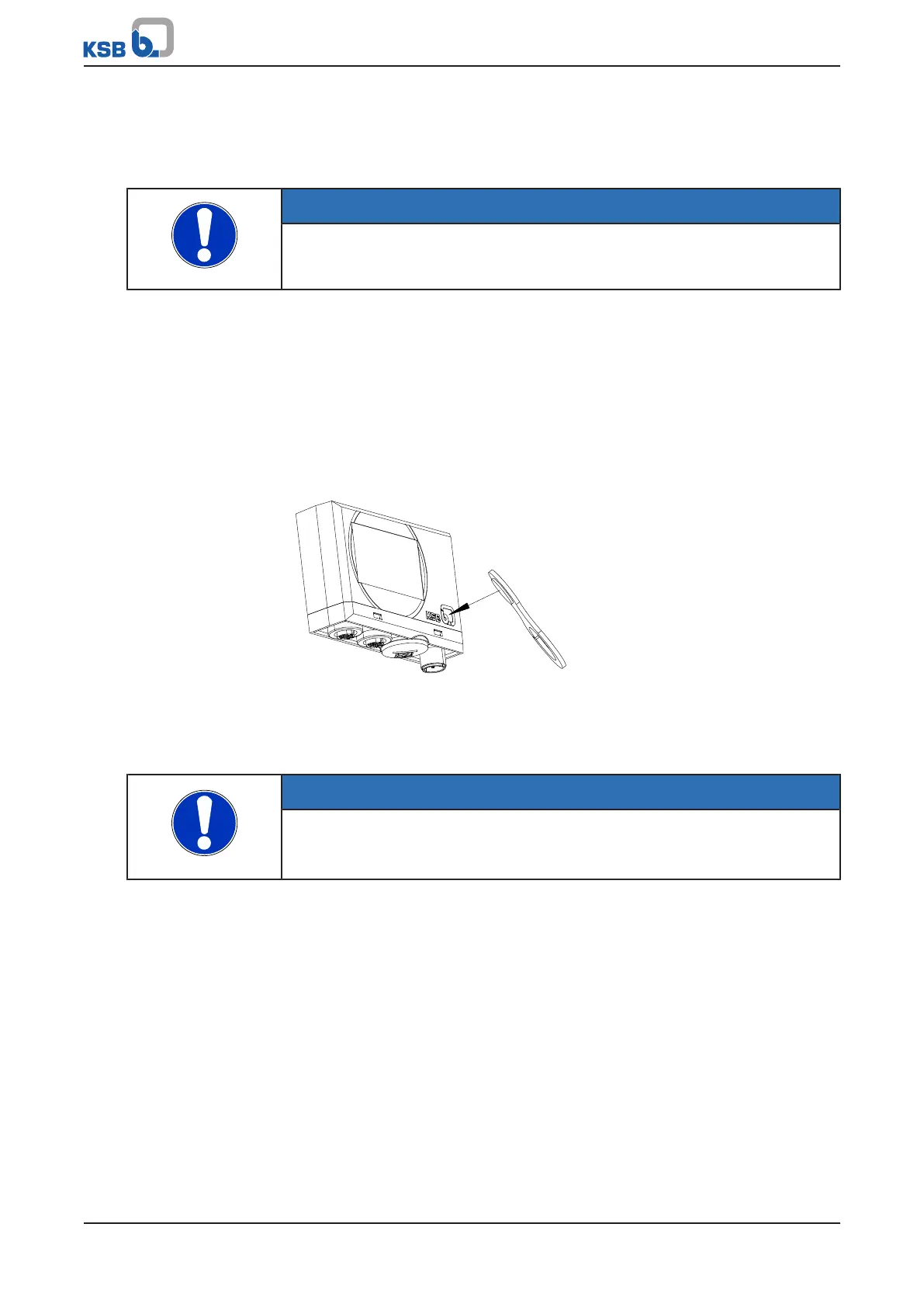
7.3.4 Resetting the analysing unit
The alarm status can be reset with the supplied magnetic clip.
Fig.5: Triggering a reset with the magnetic clip
1. Place the magnetic clip on the KSB logo until the LEDs change from red to
green.
ð The analysing unit immediately starts to monitor the leakage rate again.
NOTE
The warning status cannot be reset with the magnetic clip.
If the leakage rates sink below the warning threshold the analysing unit clears the
warning status automatically.