5 Installation at site
18 of 34
KSB Leakage Sensor
1984.8/02-EN
5.4.2 Variant for use in potentially explosive atmospheres
DANGER
Use in potentially explosive atmospheres
Explosion hazard!
▷ The device in standard design must not be used in potentially explosive
atmospheres.
▷ For use in potentially explosive atmospheres refer to the information in the
corresponding section. (ðSection2.7,Page8)
The KSB Leakage Sensor is supplied with three pre-configured cables.
▪ The power cable (connection EXT) is supplied with an open cable end, cable
length 10m.
▪ The blue sensor cable from the switching amplifier (blue terminals) to the
inductive sensor in potentially explosive atmospheres is supplied with open cable
ends, cable length 25m.
▪ The black sensor cable from the display unit (connection INT1) to the switching
amplifier (green terminals) is supplied with an open cable end, cable length
10m.
Optionally, a third cable is supplied for transmitting the leakage rate to an external
analysis device. (10m length, 4-core, open cable end and M12 connector, KSB
material number 05059190)
Pin assignment
Pin assignment of the display unit see (ðTable6)
Table7: Terminal configuration of the switching amplifier
Switching amplifier Connection cable
Terminal colour Terminal Core colour Cable
Blue 1 Brown Blue sensor cable, 2-pole connection to inductive
sensor
2 Blue
Green 5 White Black sensor cable, 4-pole connection to display unit
6 Not connected
9 Brown
10 Blue
The DIP switches of the switching amplifier remain in their factory-set position
(switches 1, 2, 3 and 4 in positionI).
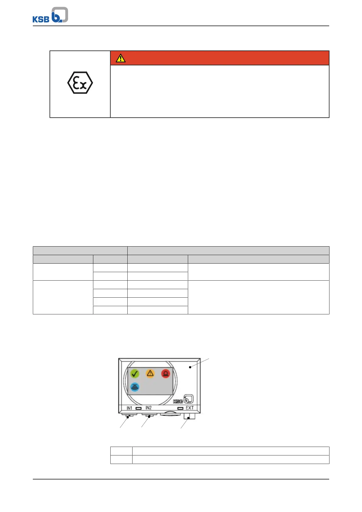
5.4.3 Connecting the power supply and message signals
Fig.2: Connection to the analysing unit
1 Analysing unit
2 M12 socket IN1