Caution
Omega
13
O --rings and V--rings must be replaced and their seats on the
shaft must be cleaned. In addition, all the sealing elements
must be fitted into the respective components before installa-
tion.
For assembling the rotor, position the pump shaft (211) secu-
rely. All fits, threads and sliding fits of the shaft must be cleaned
and coated with assembly paste.
Insert the keys required for assembly into the pump shaft (211).
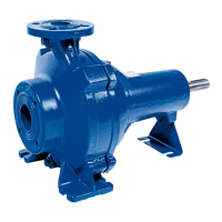
Mount the impeller (234), which has a sliding fit. When fitting the
impeller, observe the direction of rotation (see diagram below).
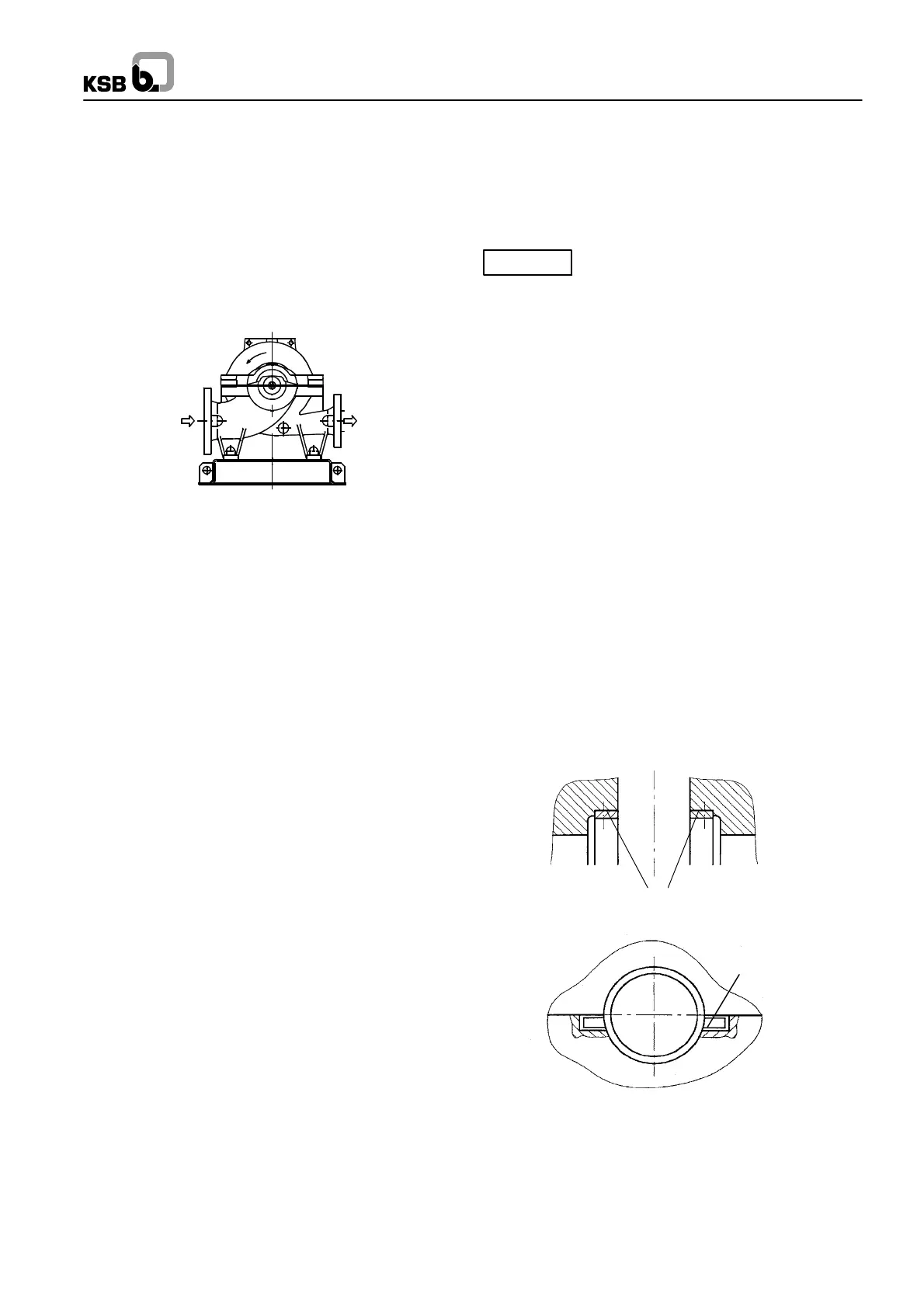
For assembling the casing wear rings (502), observe section
7.5.2 ”Replacing the casing wear rings”.
Put the casing wear rings onto the running surfaces of the im-
peller. Ensure that the bezels of the rings are on the outside (to-
wards the bearing). Insert the pins required for fixing the casing
wear rings.
The remaining components are fitted first on the movable bea-
ring side (i.e. the drive side) of the pump shaft.
Push the shaft protecting sleeve (524.01) onto the pump shaft
(211). Ensure that the groove provided engages in the key of
the impeller.
Push the shaft seal housing (441) onto the shaft and install
the shaft seal as described in section 8.1, ”Gland packing”.
Slip on V--ring (411.01).
Insert the radial shaft seal ring (421.02) into the bearing cover
(360) and push the bearing cover over the shaft.
Heat the deep--grooved ball bearing (321) and fit it onto the
pump shaft (211). It is essential to avoid one--sided pressure or
hammer blows on the outer races. The bearing is secured by
the disc (550.01) and the circlip (932).
To fit the shaft protecting sleeve (524.01), shaft seal housing
(441), V--ring (411.01) and bearing cover (360) at the non--drive
end, proceed as described above for the drive side.
Heat the deep--groove ball bearing (321) and fit it onto the
sleeve (520).
Push the sleeve (520) with deep--groove ball bearing (321) onto
the pump shaft (211) with key (940.01) inserted.
Tension the rotor parts elastically with keywayed nut (920) and
cup spring (950). For this purpose tension the cup spring (950)
to blocking point and then undo the keywayed nut (920) again
by half a turn (180_).
This measure is essential to compensate for
differences in thermal expansion between the
pump shaft (211) and the components fitted on it.
Rotor assembly is now complete.
Insert the rotor into the pump casing.
Apply Loctite 574 to the casing wear ring surfaces and the sea-
ling surfaces of the casing.
Install the rotor, making sure that the direction of rotation is cor-
rect.
Align the rotor and ensure that the fixing pins are correctly sea-
ted in the casing.
The pins (561.01) must be positioned as shown in the diagram
below.
The bearing housings (350.01) must be fastened to the bearing
brackets by means of the screwed connections (901.04), with
the sealing cap (580) inserted at the non--drive end. The seating
positions are determined by the recesses.
Fit the bearing covers.
To assemble the casing cover, apply Loctite 574 to the casing
joint surface of the lower casing half.
Tighten the flange bolts diagonally from the inside towards the
outside.
Insert the key for fitting the coupling into the pump shaft (211).
When fitting the coupling and accessories, refer to the relevant
section of the operating instructions.
Casing wear rings
(502)
561.01

 Loading...