Connections:
- 1M Pressure gauge G 1/2
- 5D Vent G 1/2
- 6B Drainage G 1/2
- 8B Leakage liq. drain G 3/4
Flanges:
- All flanges designed as plate flanges
- flange thickness to ANSI
- Connect pipes without transmitting stresses or strains
Direction of rotation:
CLOCKWISE
Keyway and key
DIN 6885 sheet 1
Shaft diameter:
Tolerance h
6
to DIN 7155
a
1
a
2
n
1
5D
h
3
h
1
DN
1
b
1
n
3
n
4
n
2
DN
2
h
2
1M
1M
d
2
s
1
s
2
6B
s
d
3
5D 5D
Z
l
3
l
2
f
l
1
d
1
8B 8B
m
1
m
2
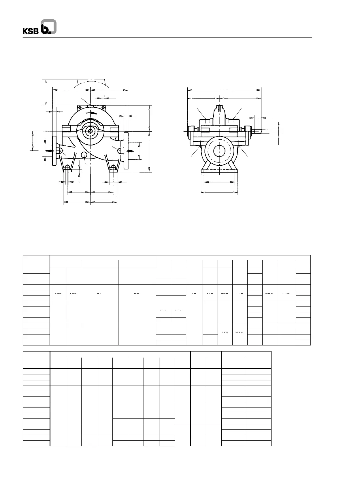
Omega
60
Dimension table Omega 80 -- 210 up to 150 -- 605
Fig. 0 N.B.: If the pump’s direction of rotation is
Direction of rotation: CLOCKWISE ANTI--CLOCKWISE, the position of
the suction and discharge nozzle is
reversed (mirror image).
Dimensions and weights All dimensions in mm
Pump
Flange dimensions Pump dimensions
Size DN
1
DN
2
s
1
s
2
a
1
a
2
d
3
f h
1
h
2
h
3
l
2
l
3
z
1)
80-210
168 340
80-270
125 80 34 29
300 300
19 415 315 140
190
300 715
380
80-370
330 330
225
450
100-250
195 390
100-310
150 100 37 32
19 415 355 170
225
300 715
450
100-375
370 370
260
520
125-230 210 420
125-290
370 370
230
460
125-365
5 4
5
5
5 4
260
520
125-500
450
450 305 610
150-290
245
490
150-360
4
4
5
5
400 200
265
530
150-460
5
4
7
450 450
305
610
150-605 600 500
5
500 300 370
740
Pump Foot dimensions Shaft
Weights [kg]
Size b
1
d
2
m
1
m
2
n
1
n
2
n
3
n
4
s d
1
l
1
Pump Water
fill
80-210 185 10
80-270 70 17,5 320 270 205 205 170 170 20 35 80 195 15
80-370 205 20
100-250 210 20
100-310 70 17,5 320 270 235 235 200 200 20 35 80 225 25
100-375 245 30
125-230 250 35
125-290
260 260 225 225
275 40
125-365
7
7,5
4
45
300 45
125-500 315 315 280 280 335 55
150-290
350 50
150-360
4
5
5
45
360 60
150-460
7
7,5
315 315 280 280
440 75
150-605
4
4
385 385 350 350
55
5
650 90
1)
z = clearance above casing cover for dismantling of the rotor

 Loading...