k
d
2
number of
holes n
Mating flange
All flanges designed as plate flanges
Omega
67
Standard flange connections
1)
:
Pump
Size
JL 1040 / GGG-NiCrNb 202
Nominal pressure acc. to:
JS 1030 / 1.4517
Nominal pressure acc. to:
DIN 2501
ISO 7005/2
BS 4504 ANSI B 16.1 DIN 2501
ISO 7005/2
BS 4504 ANSI B 16.1
125-230
125-290
125-365
125-500
PN 16 Table 16
11 Class 250 PN 25 Table 25
11 Class 250
150-290
150-360
1)
Other flange connections on request
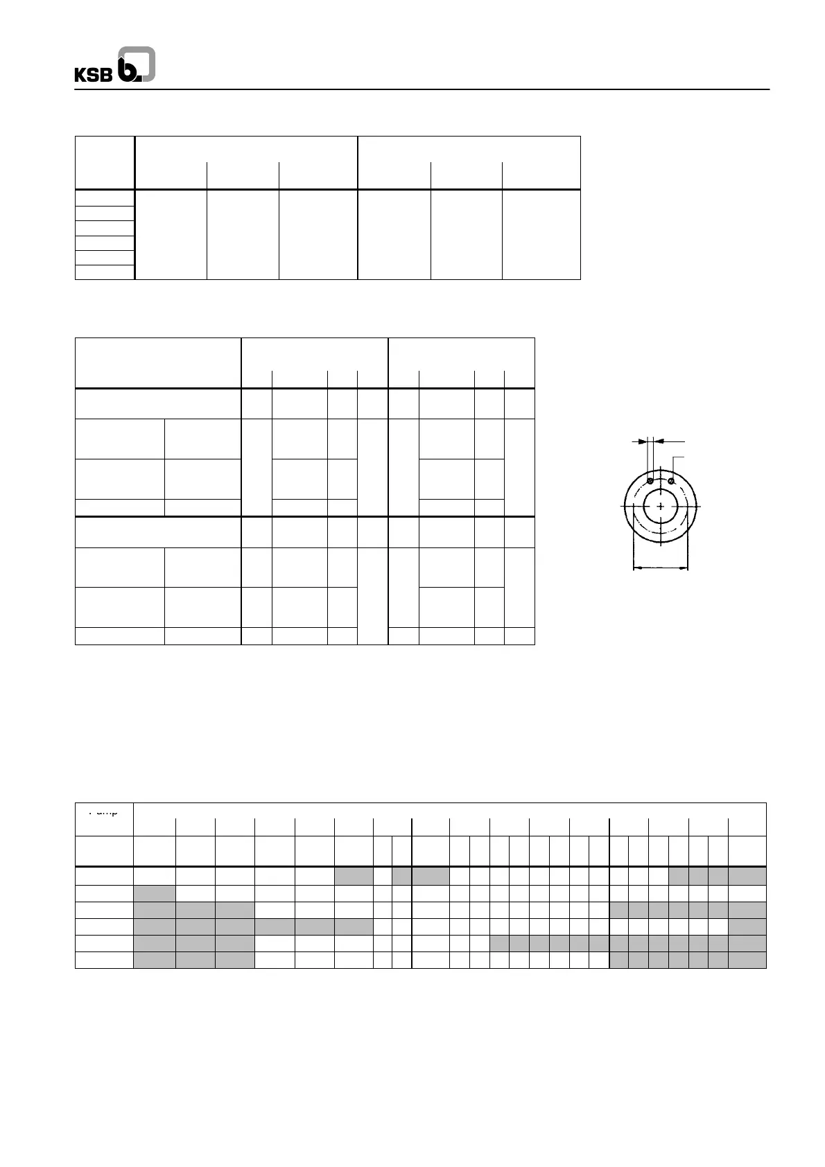
Flange dimensions -- Hole pattern All dimensions in mm
Standard
Suction flange Discharge flange
DN d
2
k n DN d
2
k n
Pump sizes 125-230 up to
125-500
200 125
ISO 7005/2
DIN 2501
BS 4504
PN 16
Table 16/11
23 (M20) 295 19 (M16) 210
ISO 7005/2
DIN 2501
BS 4504
PN 25
Table 25/11
28 (M24) 310
12
28 (M24) 220
8
ANSI B 16.1 Class 250 28 (M24) 330 23 (M20) 235
Pump sizes 150-290 up to
150-360
200 150
ISO 7005/2
DIN 2501
BS 4504
PN 16
Table 16/11
23 (M20) 295 23 240
ISO 7005/2
DIN 2501
BS 4504
PN 25
Table 25/11
28 (M24) 310
12
28 250
ANSI B 16.1 Class 250 28 (M24) 330 23 270
12
Baseplate / motor combinations
Pump
Motor Size
Size
132S 132M 160M 160L 180M 180L 200L 225S 225M 250M 280S 280M 315S 315M 315L 315
No of po-
les
4 4 4 4 4 4 2 4 4 2 4 2 4 2 4 2 4 2 4 2 4 2 4 2
125-230 4 4 4 4 4 4 5 5 5 5 6 6
125-290 4 4 4 4 4 4 5 5 5 5 5 6 6 6 6
125-365 4 4 4 4 5 5 5 5 5
125-500 4 5 5 5 5 5 6 6
150-290 4 4 4 4 5 5
150-360 4 4 4 4 5 5 5 5 5
N.B.: - The numbers listed in the table indicate the relevant baseplate numbers.
- The baseplate numbers shown in the boxes also serve to select the correct motor size for the listed pump size.
- Units comprising a motor size 315 and larger are completely assembled for verification and adjustment of the individual
components. Before shipment, the units are dismantled again and the components packed / shipped separately.

 Loading...