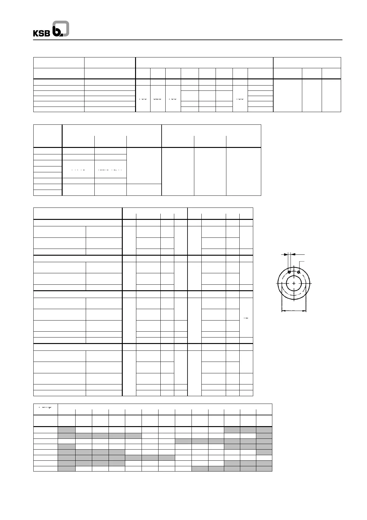
k
d
2
number of
holes n
Mating flange
All flanges designed as plate flanges
Omega
69
Baseplate-- / base frame and foundation dimensions
All dimensions in mm
Baseplate
Size
Baseplate
Size
Baseplate and foundation dimensions Foundation bolts
No. Drawing no. b
2
G
1
G
2
l
3
l
4
l
5
h
8
Weight Size
V
N
L
[kg]
7 0W 384 174-00 880 820 960 1660 730 730 120 157
8
1
) 0W 384 175-00 1870 835 835 185
9
1)
0W 384 176-00
204
10
1)
0W 384 478-00 700 620 750
7
5
5
180 208
M 20x320 100 320
14
1)
0W 384 479-00
2170 985 985
210
15
1)
0W 384 480-00 2320 1060 1060 215
1)
Base frame
Standard flange connections
2):
Pump
Size
JL 1040 / GGG-NiCrNb 202
Nominal pressure acc. to:
JS 1030 / 1.4517
Nominal pressure acc. to:
DIN 2501
ISO 7005/2
BS 4504 ANSI B 16.1 DIN 2501
ISO 7005/2
BS 4504 ANSI B 16.1
150-460 PN 16 Table 16/11
150-605 PN 25 Table 25/11 Class 250
200-320
200-420
PN 16 Table 16/11
200-520
PN 25 Table 25
11 Class 250
200-670 PN 25 Table 25/11
250-370
300-300
a
e
ass
5
2)
Other flange connections on request
Flange dimensions -- Hole pattern All dimensions in mm
Standard
Suction flange Discharge flange
DN d
2
k n DN d
2
k n
Pump sizes 150-460 and 150-605 200 150
ISO 7005/2, DIN 2501
BS 4504
PN 16
Table 16/11
23 (M20) 295 23 (M20) 240
ISO 7005/2, DIN 2501
BS 4504
PN 25
Table 25/11
28 (M24) 310
12
28 (M24) 250
ANSI B 16.1 Class 250 28 (M24) 330 23 (M20) 270
12
Pump sizes 200-320 up to 200-670 250 200
ISO 7005/2, DIN 2501
BS 4504
PN 16
Table 16/11
28 (M24) 355 23 (M20) 295
ISO 7005/2, DIN 2501
BS 4504
PN 25
Table 25/11
31 (M27) 370
12
28 (M24) 310
ANSI B 16.1 Class 250 28 (M24) 387 28 (M24) 330
Pump sizes 250-370 300 250
ISO 7005/2, DIN 2501
BS 4504
PN 10
Table 10/11
23 (M20) 400
23 (M20) 350
ISO 7005/2, DIN 2501
BS 4504
PN 16
Table 16/11
28 (M24) 410
28 (M24) 355
12
ISO 7005/2, DIN 2501
BS 4504
PN 25
Table 25/11
31 (M27) 430 16 31 (M27) 370
ANSI B 16.1 Class 125 28 (M24) 432
12
28 (M24) 362
ANSI B 16.1 Class 250 31 (M27) 451
16
28 (M24) 387
16
Pump sizes 300-300 350 300
ISO 7005/2, DIN 2501
BS 4504
PN 10
Table 10/11
23 (M20) 460 23 (M20) 400
ISO 7005/2, DIN 2501
BS 4504
PN 16
Table 16/11
28 (M24) 470 16 28 (M24) 410
ISO 7005/2, DIN 2501
BS 4504
PN 25
Table 25/11
34 (M30) 490 31 (M27) 430 16
ANSI B 16.1 Class 125 28 (M24) 476
12
28 (M24) 432
12
ANSI B 16.1 Class 250 31 (M27) 514
20
31 (M27) 451
16
Baseplate / motor combinations
Pump
Motor Size
Size
180L 200L 225S 225M 250M 280S 280M 315S 315M 315L 315 355 400
No of
poles
4 4 4 4 4 4 4 4 4 4 4 4 4
150-460 7 7 7 7 8 8 8 8 8
150-605 8 8 8 8 9 9 14
200-320 7 7 7 7 7 8 8
200-420 7 7 7 7 8 8 8 8 9
200-520 7 8 8 8 8 10 10 15
200-670 8 8 10 10 15 15
250-370 7 8 8 8 8 10
300-300 7 7 7 7 8 8 8
N. B.: - The numbers listed in the table indicate the relevant baseplate numbers.
- The baseplate numbers shown in the boxes also serve to select the correct motor size for the listed pump size.
- Units comprising a motor size 315 and larger are completely assembled for verification and adjustment of the individual components.
Before shipment, the units are dismantled again and the components packed / shipped separately.

 Loading...