RDLO
Page 16 of 24
The bearings are secured by the disc (550.1) and
the circlip (932).
To fit the spacer sleeve (525.3), shaft seal housing
(441) altogether with mechanical seal or gland
packing, shaft protecting sleeve (524.1 or 524.2),
seal cover (471), spacer sleeve (525.1) and V-ring
(411.1) as well as bearing cover (360) at the
floating bearing side, proceed as described above
for the driven end.
Heat the deep-groove ball bearing (321) to max.
80°C and fit it on the sleeve (520).
Slide the sleeve (520) with deep-groove ball
bearing (321) and disc (550.1) on the pump shaft
(211) - with the key (940.1) inserted.
It is imperative to observe the
instructions on servicing of the
bearings given in section 7.2.3.
For information on the bearing sizes please refer to
the technical annex, section 9.2.
Join the rotor parts elastically with grooved nut
(920.4) and disc spring (950.2). For this purpose
tighten the disc spring (950.2) as indicated in the
following table.
Thread size of
grooved nut (920.4)
Tighten by
M55 x 2
1 turn
(360 degrees)
M60 x 2
1 turn
(360 degrees)
M80 x 2
1 ¼ turns
(450 degrees)
M90 x 2
1 ½ turns
(540 degrees)
M100 x 2
1 ½ turns
(540 degrees)
This measure is essential to
compensate differences in
thermal expansion of the pump shaft (211) and the
components fitted on it.
Then tighten the safety screw (914.1) in order to
lock the grooved nut (920.4) in position.
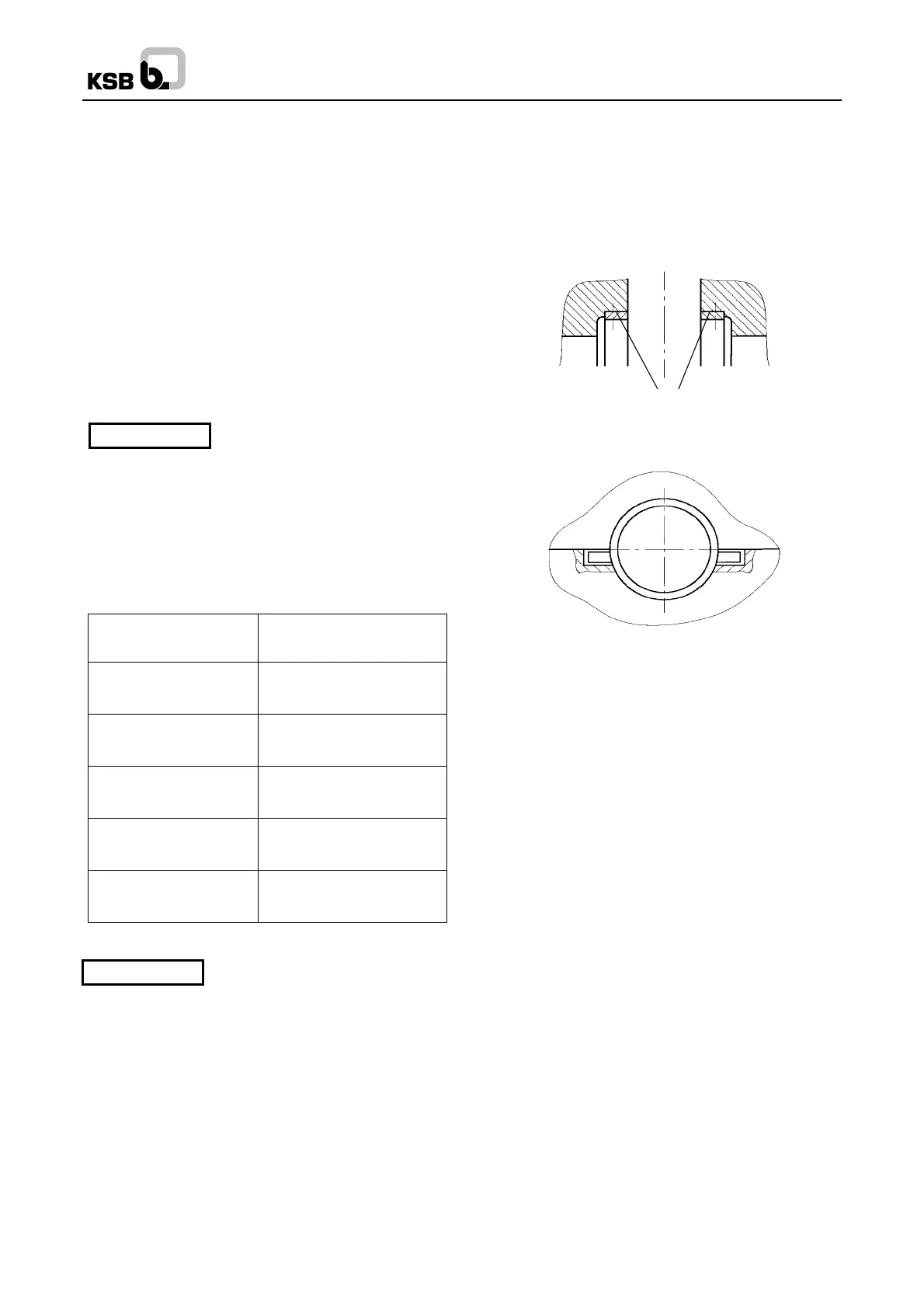
The ribs on the shaft seal housings (441) have to
be arranged at an angle of 45° or 50° to the top in
relation to the horizontal line. The position of the
grooved pin (561.2) is then vertically to the bottom.
Prior to inserting the pump rotor in the pump casing,
apply a liquid sealant to the surfaces of the casing
wear rings and the sealing faces of the shaft seal
housing (441) as described in the assembly
instruction.
Insert and align the rotor, making sure that the
direction of rotation is correct and the grooved pins
(561.1 and 561.2) are correctly seated in the
casing; see sectional drawing and diagram below.
Spaltringe
Casing wear rings
Fasten the bearing housings (350.1 and 350.2) to
the lower part of the volute casing (102) by means
of the hexagon head bolts (901.4).
Place the V-rings (411.1) in their correct positions,
and fit the V-ring (411.2) and adapter (145).
Prior to fitting the upper part of the volute casing
(102), clean both casing split flanges meticulously.
Apply a thin film of liquid sealant to the entire
surface of the lower casing split flange as described
in the assembly instruction.
Carefully place the upper part of the volute casing in
position. Centring is effected by the casing wear
rings and the shaft seal housing (441).
Tighten the casing split flange bolts (901.1) in
diagonally opposite sequence, starting with the
bolts nearest the pump centreline. Fasten the
bearing housings (350.1 and 350.2) to the upper
part of the volute casing (102) by means of the
hexagon head bolts (901.4).
Insert the key (940.3) for fitting the coupling in the
pump shaft (211).
When fitting the coupling and accessories, observe
the individual operating instructions in the sections
9.3, 9.5, and 9.6.
Caution
Caution
 Loading...


