Table 7: Bearing design
KSB designation FAG designation SKF designation
B.MUA B-MP-UA BECBM
Table 8: Standard bearing assembly
Bearing bracket Rolling element bearings
Pump end Motor end
B02 NU211C3 2 x 7309B-MUA
B03 NU213C3 2 x 7311B-MUA
B05 NU316C3 2 x 7315B-MUA
B06 NU324C3 2 x 7224B-MUA
B07 NU324C3 2 x 7324B-MUA
Table 9: Reinforced bearing assembly (triple bearing assembly)
Bearing bracket Rolling element bearings
Pump end Motor end
B02 NU211C3 3 x 7309B-MUA
B03 NU213C3 3 x 7311B-MUA
B05 NU316C3 3 x 7315B-MUA
B06 NU324C3 3 x 7224B-MUA
B07 NU324C3 3 x 7324B-MUA
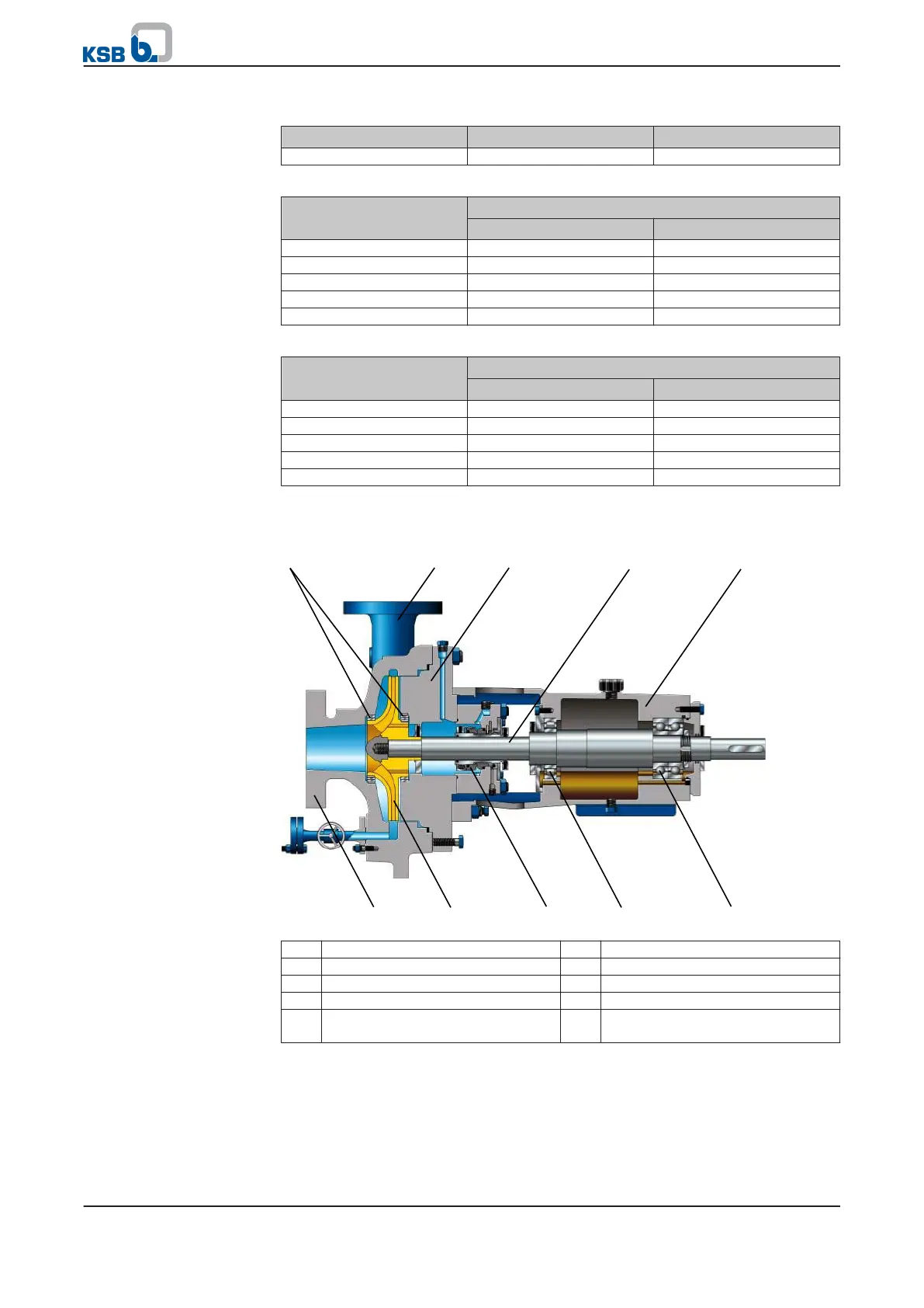
4.5 Configuration and function
1 Clearance gap 2 Discharge nozzle
3 Casing cover 4 Shaft
5 Bearing bracket 6 Suction nozzle
7 Impeller 8 Shaft seal
9 Rolling element bearing, pump
end
10 Rolling element bearing, motor
end
The pump is designed with an axial fluid inlet and a radial or tangential outlet. The
hydraulic system runs in its own bearings and is connected to the motor by a shaft
coupling.
Bearings used
Design
4 Description of the Pump (Set)
18 of 76
RPH