3. Check the alignment of the coupling halves with a dial gauge (see drawing
"Checking the spacer-type coupling with a dial gauge").
Admissible run-out of coupling face (axial) maximum 0.1 mm.
Admissible radial deviation, measured over the complete circumference,
maximum 0.2 mm.
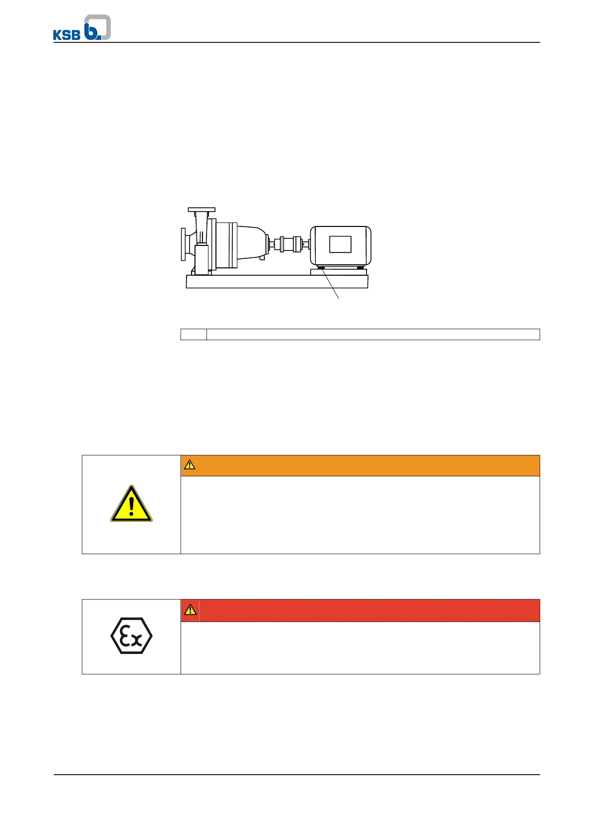
5.7 Aligning the pump and motor
After having installed the pump set and connected the piping, check the coupling
alignment and, if required, re-align the pump set (with the motor).
Any differences in shaft centre height between the pump and the motor are
compensated by means of shims.
Fig. 10: Pump set with shim
1 Shim
✓ The coupling guard and the footboard for the coupling guard, if any, have been
removed.
1. Check the coupling alignment.
2.
Unscrew the hexagon head bolts at the motor.
3. Insert shims underneath the motor feet until the difference in shaft centreline
height has been compensated.
4. Re-tighten the hexagon head bolts.
5. Check that the coupling and shaft can easily be rotated by hand.
WARNING
Unprotected rotating coupling
Risk of injury by rotating shafts!
▷ Always operate the pump set with a coupling guard.
If the customer specifically requests not to include a coupling guard in KSB's
delivery, then the operator must supply one!
▷ Observe all relevant regulations for selecting a coupling guard.
6. Re-install the coupling guard and the footboard for the coupling guard, if any.
7. Check the distance between coupling and coupling guard.
The coupling and coupling guard must not come into contact.
DANGER
Risk of ignition by frictional sparks
Explosion hazard!
▷ Choose a coupling guard material that is non-sparking in the event of
mechanical contact (see DIN EN 13463-1).
5 Installation at Site
26 of 76
RPH