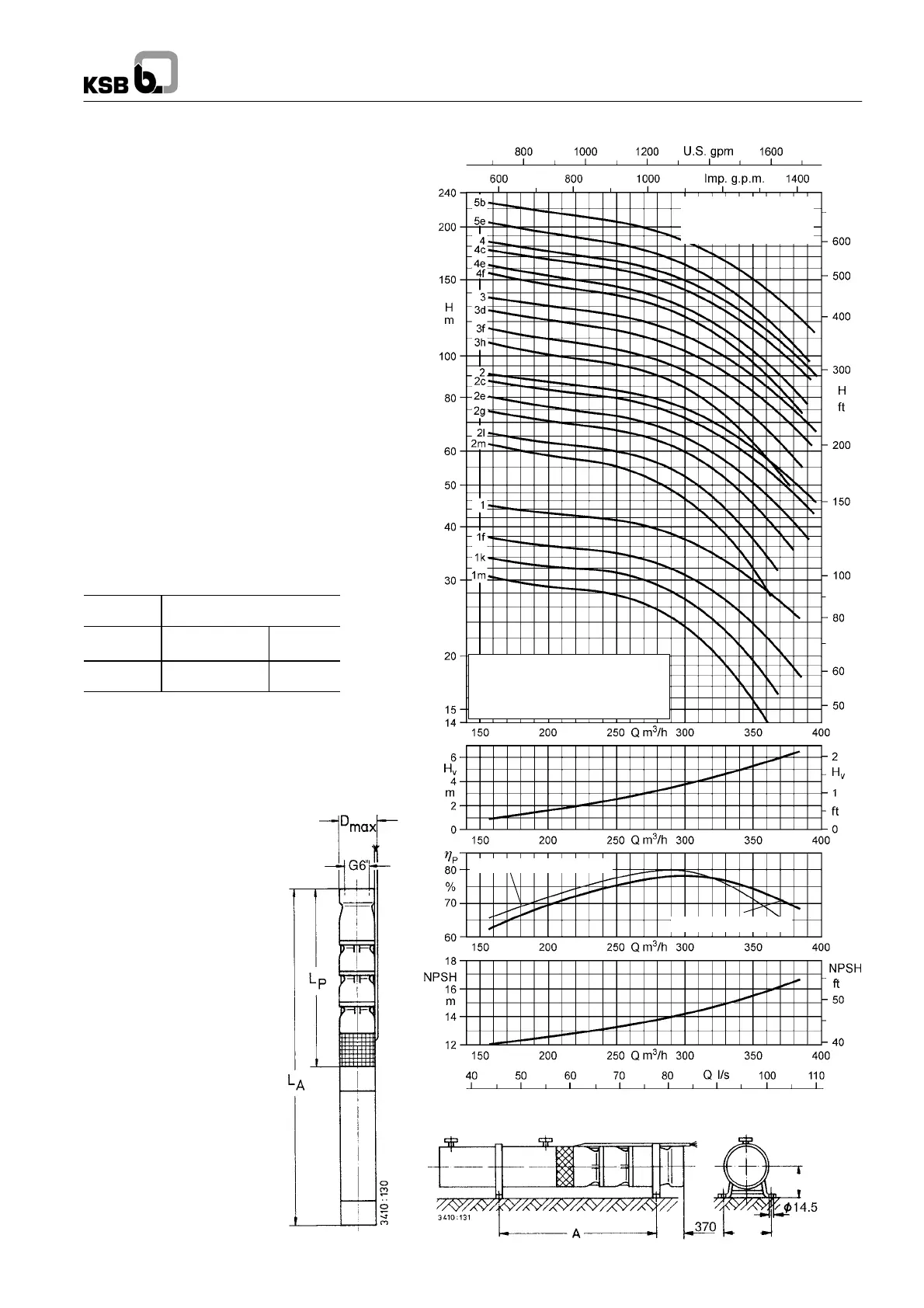
UPA 250C -- 250 /..
(Tolerances to
ISO 9906 Class 2)
Optimum impeller dia. ”h”
Maximum impeller dia.
Operating range:
Q
min
=60m
3
/h
Q
max
= End of characteristic curve
250
400
60 Hz UPA 200B, 250C
71
UPA 250C -- 250 / ..
The characteristic curves shown are for preliminary
selection only. Exact selection data will be provided
in our quotation.
Selection
The pressure losses H
v
in the check valve are not
considered in the pump characteristic curves.
For more details and a selection example refer to
page 8.
Legend ...
H
v
: Head losses in the check valve
η
p
: Pump efficiency
(not considering check valve)
NPSH: Net positive suction head
required by the pump
Pump End G 6’’ / DN 150
The information is based on the model “with check
valve / connection branch and threaded end”.
The changes in the main dimensions of the “flanged
end” model are specified in the table below.
Check valve / connection branch with:
Threaded
end G 6’’
Flanged end
DN 150
Length
mm
Length
mm
Outside dia.
mm
229 179 (PN 10/16)
179 (PN 25/40)
285
300
Threaded end to DIN ISO 228, Part 1.
Flange mating dimensions to DIN EN 1092--2.
 Loading...