60 Hz
UPA 300, 350
82
UPA 350 -- 128 for Well Diameters of 350 mm (14 inches) and Above
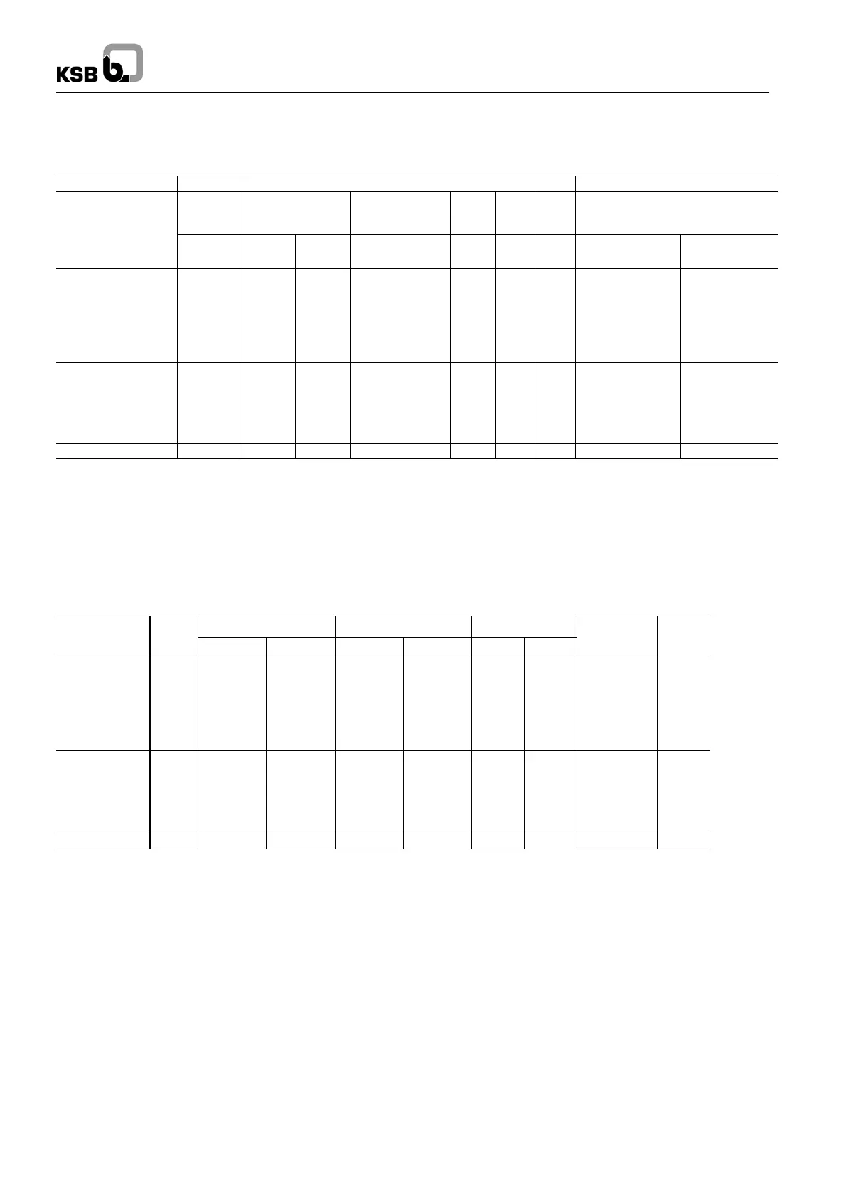
Pumps with submersible motors for ... -- Type of current / voltage three-phase (3~) / 460 V...........................
-- Starting d.o.l. (D) or star-delta (Y-∆).......................................
Pump unit Pump Motor Motor lead
2)
,flat
Discharge
head
Q=0m
3
/h
Rated
power
Max. temperature
of the fluid handled
v ≥ 0.5 m/s
Rated
current
Effi-
ciency
Power
factor
Number x cross-section of
conductors (use under water,
460 V and ≤ 30 _C)
UPA 350 -- 128/ ... + ...
H
o
m
P
N
kW
P
N
hp
t
max
1)
_C
I
N
A
η
M
%
cos φ
-- --
D.o.l.
mm
2
Y-∆
mm
2
1l + UMA 200D 55/21
1k + UMA 200D 75/21
1h + UMA 200D 90/21
1f + UMA 250D 110/21
1d + UMA 250D 132/21
1b + UMA 250D 160/21
1 + UMA 250D 190/21
56.9
65.8
74.9
83.2
91.9
100.0
109.0
60.0
78.0
100.0
115.0
135.0
155.0
185.0
80.5
104.6
134.1
154.2
181.0
207.9
248.1
32
32
31
32
32
31
31
101.0
134.0
169.0
195.0
222.0
254.0
311.0
86.8
87.5
88.2
88.7
89.3
89.6
90.2
0.86
0.84
0.85
0.84
0.86
0.86
0.83
4x16
3/4 x 10 II
3)
3/4 x 16 II
3)
3/4 x 16 II
3)
3/4 x 25 II
3)
3/4 x 25 II
3)
3/4 x 35 II
3) 5)
3/4 x 6.0
4)
3/4 x 10
4)
3/4 x 16
4)
3/4 x 25
4)
3/4 x 25
4)
3/4 x 35
4) 5)
3/4 x 35
4) 5)
2h + UMA 300D 250/22
2g + UMA 300D 250/22
2e + UMA 300D 250/22
2c + UMA 300D 250/22
2b + UMA 300D 300/22
2 + UMA 300D 300/22
154.9
162.6
174.6
189.0
204.1
220.4
205.0
220.0
245.0
280.0
315.0
360.0
274.9
295.0
328.6
375.5
422.4
482.8
62
62
60
58
59
57
347.0
367.0
400.0
450.0
513.0
575.0
89.5
89.7
90.1
90.3
90.7
91.0
0.83
0.84
0.86
0.87
0.85
0.87
3/3x70 II + 1x35
3) 6)
3/3x70 II + 1x35
3) 6)
3/3x70 II + 1x35
3) 6)
3/3x70 II + 1x35
3) 6)
6x95 II + 1x50
3) 7)
6x95 II + 1x50
3) 7)
6x95 + 1x50
4) 7)
6x95 + 1x50
4) 7)
6x95 + 1x50
4) 7)
6x95 + 1x50
4) 7)
6x95 + 1x50
4) 7)
6x95 + 1x50
4) 7)
3c + UMA 300D 400/22 282.3 415.0 556.5 56 658.0 91.1 0.87 6x95 II + 1x50
3) 7)
6x95 + 1x50
4) 7)
1)
Also see pages 3 and 75
2)
3/4 = 1 x 3-core + 1 x 4-core, flat, 90_ spacing.
3)
2 cables in parallel.
4)
Delta wiring in the cable connector or control cabinet.
5)
1 x 3--core flat + 1 x 4--core round.
6)
2 x 3--core flat + 1 x 1--core round.
7)
6 x 1--core round + 1 x 1--core round.
Dimensions / Weights / Horizontal Installation
1)
L
P
L
A
¶ mm m
A
in ¶ kg D
max
¶ mm
Installation
2)
A
UPA 350 -- 128/ ..
¶ mm
Standard Special Standard Special D.o.l Y-∆
¶ mm
1l
1k
1h
1f
1d
1b
1
898
898
898
898
898
898
898
2239
2459
2639
2427
2557
2667
2817
2239
2459
2639
2427
2557
2667
2817
289
328
360
432
476
513
564
308
347
379
452
496
533
584
316
320
324
324
334
334
343
322
320
324
334
334
343
357
v+h
v+h
v
3)
v+h
v+h
v+h
v
3)
1119
1229
-- --
1213
1278
1333
-- --
2h
2g
2e
2c
2b
2
1108
1108
1108
1108
1108
1108
3181
3181
3181
3181
3361
3361
3181
3181
3181
3181
3361
3361
764
764
764
764
842
842
793
793
793
793
871
871
360
360
360
360
341
341
360
360
360
360
341
341
v
4)
v
4)
v
4)
v
4)
v
4)
v
4)
-- --
-- --
-- --
-- --
-- --
-- --
3c 1308 3681 3681 936 970 341 341 v
3) 4)
-- --
1)
Including check valve with threaded end and standard motor leads.
2)
v = vertical; h = horizontal.
3)
Horizontal installation on request.
4)
Horizontal installation only with bearing pedestals of special design.