– For the required sensor length refer to the list of measuring points. Verify
the length at the site of installation.
– Insert the sealing element. Screw in the resistance thermometer or
thermocouple.
–
Run the connecting cables in cable ducts until just before reaching the
measuring point and have them connected by authorised personnel.
▪ Differential pressure measurement:
– Fasten the monitoring equipment for the differential pressure to the holder
provided on the sole plate.
– Connect the instrument leads to the connecting points provided and install
them in accordance with the conditions on site.
– Run the connecting cables in cable ducts until just before reaching the
measuring point and have them connected by authorised personnel.
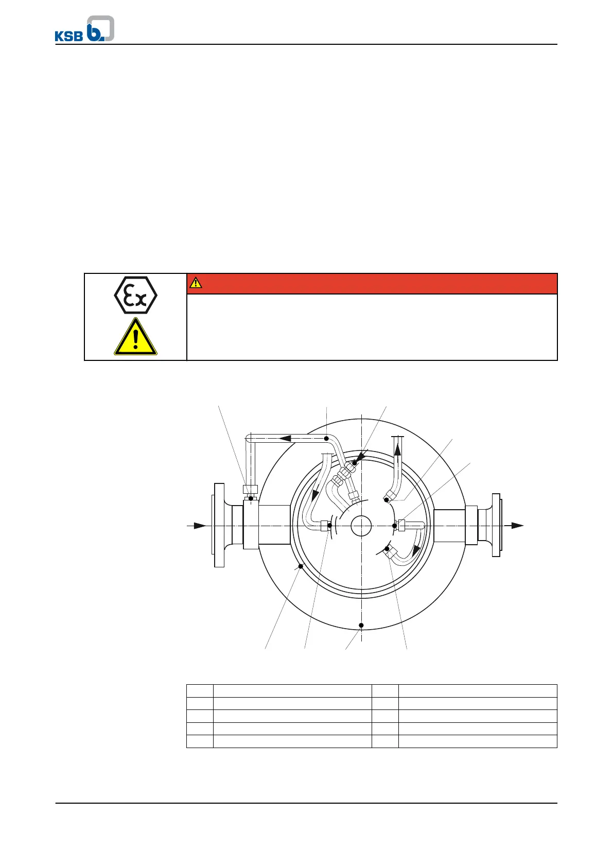
5.11 Fitting the auxiliary connections
DANGER
Improper connection of auxiliary lines
Explosion hazard from escaping leakage or fluid!
▷ Correctly install the auxiliary lines.
▷ Observe the maintenance and monitoring schedules.
5B
7A.1
7E.28B7E.1
15E 15A
7A.2
10E
Fig. 9: Installing the connecting lines (example)
5B Venting 8B Leakage drain
7A.1 Outlet, cooling liquid 10E Inlet, sealing liquid
7A.2 Outlet, cooling liquid 15A Outlet, balancing liquid
7E.1 Inlet, cooling liquid 15E Inlet, balancing liquid
7E.2 Inlet, cooling liquid
✓ The mechanical seal has been properly installed.
✓ The bearings have been fitted properly.
5 Installation at Site
36 of 78
WKTR