2 SETUP
4
Info
The procedure in the event of transport damage is
described in the Customer Service Manual.
S04116-01
–
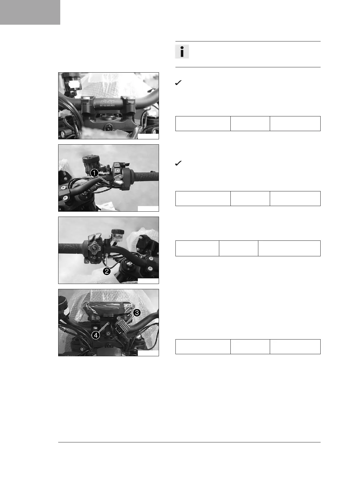
Position the handlebar.
The markings of the handlebar scale are located centrally
between the handlebar clamp.
– Position the handlebar clamp. Mount and tighten the screws
evenly.
Guideline
Screw, handlebar
clamp
M8 20 Nm (14.8 lbf ft)
S05686-10
– Position the brake assembly on the handlebar.
– Position brake assembly clamp on the handlebar.
The holding lug of the clamp engages in the combination
switch.
–
Mount and tighten screws
1
.
Guideline
Screw, brake assem-
bly
5 Nm (3.7 lbf ft)
S05687-10
– Position the clutch assembly on the handlebar.
–
Mount and tighten screw
2
.
Guideline
Screw, clutch
assembly
M6 5 Nm (3.7 lbf ft)
Loctite
®
243™
S05688-10
–
Unplug connector
3
.
– Position the combination instrument rack on the handlebar.
–
Mount screw
4
, but do not tighten it yet.
– Move the combination instrument into the desired position.
–
Tighten screw
4
.
Guideline
Screw, combination
instrument clamping
M6 2 Nm (1.5 lbf ft)
–
Plug in connector
3
with sleeve.
(SUPER DUKE RR)
– Remove the mounted clutch and hand brake lever.
 Loading...