4 Installation Kübler Group
12 - EN HB Profibus Interface - R67068.0002 - 01
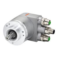
Inter-
face
Type of
connec-
tion
Cable (isolate unused wires individually before
commissioning)
Connector
3 2 Connector
Bus IN
Signal – PB_A – PB_B Shield
Pin 1 2 3 4 5
Bus OUT
Signal BUS_
VDC
PB_A BUS_
GND
PB_B Shield
Pin 1 2 3 4 5
Voltage supply
Signal +V – 0 V –
Pin 1 2 3 4
3 1 Terminal strip
Bus IN
Signal B A 0 V + V
Pin 1 2 3 4
Bus OUT
Signal B A 0 V + V
Pin 7 8 5 6
PROFIBUS connection internal terminal strip
NOTICE
Bus connection with separate voltage supply and PG screwed
fitting.
The bus cover must be removed to access to the internal terminal
strip.
• Unscrew the two bus cover screws and remove the bus cover from
the encoder.
• When re-tightening, take care to tighten the screws with a torque of
0.5 Nm.
Proceed as follows to connect the terminal strip :
a) Guide the incoming bus cable through the left screwed cable fitting and
b) connect the bus cable to terminal (B) and terminal (A). Apply the cable shield on the
cable fitting.
c) If there are further devices in the bus strand : Guide the continuing cable through the right
screwed cable fitting and connect it to terminal (B) and terminal (A).