DIESEL ENGINE
05
SERIES
WSM,
01642
119OOF103W
I
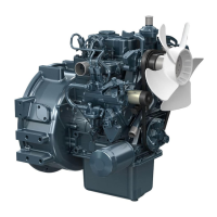
Fan Drive Pulley
1,
Set the stopper to the flywheel.
2.
Remove the crankshaft screw
(I),
3.
Draw out the fan drive pulley
(2)
with a puller,
(When reassembling)
Install the pulley
(D905,
D1005, D1105) to the crankshaft,
aligning the marks
(3)
on them.
Tightening torque
142.2
to
152.0
Nm
14.5
to
15.5
kgfm
Crankshaft screw
(Serial
No
:
-
604086)
104.9
to
112.1
ft-lbs
235.4
to
245.2
Nm
24.0
to
25.0
kgfm
Crankshaft screw
(Serial
No
:
604087
-)
173.6
to
180.8ft-lbs
(1)
Crankshaft Screw
(2)
Fan Drive Pulley
(3)
Aligning Marks
0
164051
0360
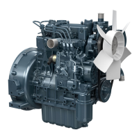
Gear Case
1.
Remove the gear case,
(When reassembling)
Apply a liquid gasket (Three Bond
1215
or
equivalent) to
Grease thinly to the oil seal, and install
it,
ensuring the
lip
sides of the gear case gasket.
not come
off.
both
does
Length of the gear case mounting bolts (refer to the figure)
A:45mm E:68mm
B:50mm F:80mm
C:55mm
G
:
Nut
D:59mm
01640S10370
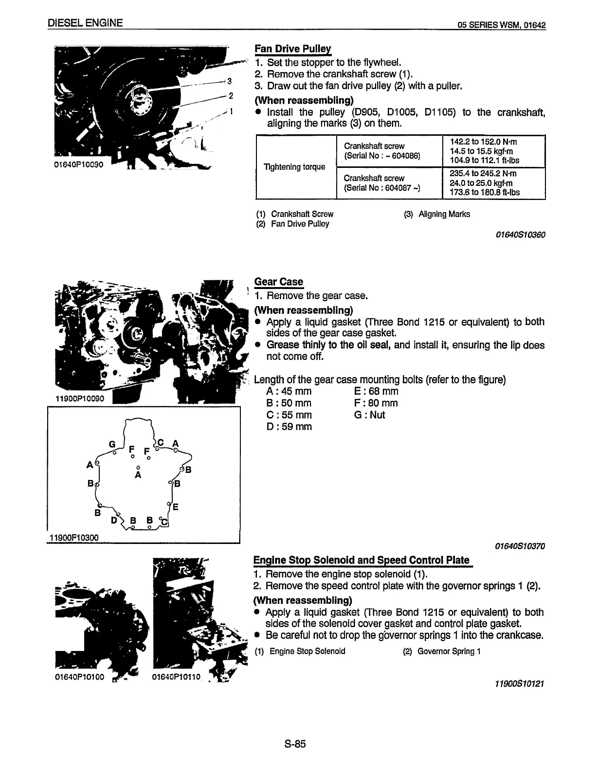
Engine Stop Solenoid and Speed Control Plate
1.
Remove the engine stop solenoid
(1).
2.
Remove the speed control plate with the governor springs
I
(2).
(When reassembling)
Apply a liquid gasket (Three Bond
1215
or
equivalent) to both
Be careful not to drop the governor springs
1
into the crankcase.
sides
of
the solenoid cover gasket and control plate gasket.
(1)
Engine
Stop
Solenoid
(2)
Governor Spring
1
11900s10121
5-85
Redistribution or publication of this document,
by any means, is strictly prohibited.
 Loading...