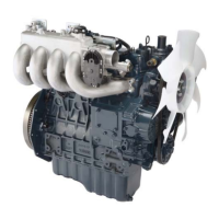
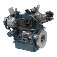
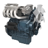
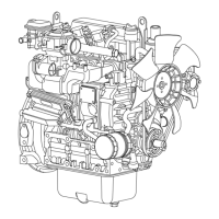
Do you have a question about the Kubota WSM 05-E3B Series and is the answer not in the manual?
Describes the manual's division into General, Mechanism, and Servicing sections.
Explanation of safety symbols and the importance of reading safety regulations.
Essential steps to take before beginning any maintenance or repair work.
Guidelines for safely starting the engine, avoiding hazardous methods.
General safety rules for working on the engine, including PPE and handling hot parts.
Precautions against fire hazards involving fuel, sparks, and battery gas.
Ensuring ventilation and safety measures for handling battery acid.
Instructions for environmentally sound disposal of engine fluids.
Ensuring availability of first aid, fire extinguishers, and emergency contacts.
Technical specifications for D1005, D1105-E3B, and D1105-T-E3B engine models.
Technical specifications for D1305-E3B, V1505-E3B, and V1505-T-E3B engine models.
Technical specifications for BG series engine models.
Physical dimensions for D1005, D1105-E3B, and D1105-T-E3B engine models.
Physical dimensions for the D1305-E3B engine model.
Physical dimensions for V1505-E3B and V1505-T-E3B engine models.
Physical dimensions for BG series engine models.
Physical dimensions for the D1305-E3BG engine model.
How to identify the engine model and serial number for service.
Decoding the engine serial number to determine manufacture date.
Information on E3B engine designation for emission standards and output classification.
Standard cylinder numbering sequence starting from the gear case.
Important safety and procedural precautions for engine work.
A checklist of maintenance items and their recommended service intervals.
Guidance on selecting appropriate engine oils and fuels based on specifications.
Procedure for checking the engine oil level using the dipstick.
Steps for checking coolant level and adding coolant or anti-freeze.
Procedure for the first engine oil change at 50 hours, including oil specifications.
Instructions for replacing the engine oil filter cartridge.
Checking fuel hoses and clamps, and bleeding the fuel system.
Procedure for cleaning the air cleaner element.
Procedure for cleaning the fuel filter element.
Checking and adjusting fan belt tension.
Inspecting the fan belt for damage and wear.
Checking the battery electrolyte level.
Procedure for changing engine oil at 200-hour intervals.
Replacing the oil filter cartridge as part of 200-hour maintenance.
Checking radiator hoses and clamp bands.
Checking the intake air line and clamps.
Replacing the fuel filter cartridge every 400 hours.
Cleaning the engine's water jacket and radiator interior.
Information on anti-freeze types, freezing/boiling points, and mixing.
Procedure for replacing the fan belt.
Procedures for charging the battery, including slow and quick methods.
Checking battery specific gravity with a hydrometer.
Procedure for replacing the air cleaner element annually.
Checking and adjusting valve clearance.
Checking nozzle spraying condition, fuel injection pressure, and valve seat tightness.
Inspecting the turbocharger for leaks and radial clearance.
Procedure for checking and adjusting injection timing.
Testing fuel tightness of injection pump components.
Procedure for replacing the intake air line.
Procedure for replacing the engine battery.
Procedure for replacing radiator hoses and clamp bands.
Procedure for replacing fuel hoses and clamp bands.
Steps for changing the radiator coolant.
Additional information on anti-freeze properties and mixing.
Tools for measuring engine compression via nozzle or glow plug holes.
Tool for measuring lubricating oil pressure.
Specifications for constructing an injection pump pressure tester.
Specifications for a tool to replace valve guides.
Specifications for tools used in replacing bushings.
Specifications for a tool to secure the flywheel.
Specifications for tools used to replace crankshaft bearing 1.
Specifications for tools used to replace governor gear holder bushings.
Specifications for components of the crank sleeve setter tool.
Explanation of the closed breather system's role in re-combusting blow-by gas.
Description of the half-floating head cover's function in reducing engine noise.
Detailed explanation of the three-lever fork lever governor's mechanism.
How the governor system controls fuel supply during overload.
Description of the two-lever fork lever governor for BG series.
Explanation of the boost compensator's role in reducing smoke during acceleration.
Diagnosing and resolving issues when the engine does not start.
Identifying causes for rough running and solutions.
Diagnosing problems indicated by white, blue, or black exhaust gases.
Addressing oil leaks into the exhaust or suction pipes.
Resolving issues related to reduced engine power.
Diagnosing and fixing high engine oil consumption.
Addressing fuel or water contamination in the engine oil.
Diagnosing and resolving low oil pressure.
Addressing high oil pressure and engine overheating issues.
Diagnosing and resolving rapid battery discharge problems.
Specifications for valve clearance, compression, head flatness, and valve components.
Specifications for valve springs, rocker arms, push rods, tappets, and timing gears.
Specifications for gears, camshafts, piston pins, and bushings.
Specifications for piston ring gaps and connecting rod alignment.
Specifications for oil clearances between crankshaft components and bearings.
Specifications for crankshaft side clearance and cylinder bore I.D.
Specifications for engine oil pressure at idle and rated speeds.
Specifications for fan belt tension, thermostat temperatures, and radiator cap.
Specifications for injection timing, fuel tightness, and nozzle pressure.
Specifications for glow plugs, starters, and alternators.
Torque specifications for common screws, bolts, and nuts.
Specific torque values for critical engine components.
Procedure for testing engine compression pressure.
Procedure for checking and adjusting valve clearance.
Procedure for checking engine oil pressure.
Procedure for checking and adjusting fan belt tension.
Checking fan belt condition and performing radiator leak tests.
Testing the thermostat's opening temperatures.
Procedure for checking and adjusting injection timing.
Testing fuel tightness of injection pump components.
Checking nozzle spraying condition, pressure, and valve seat tightness.
Nozzle holder procedures and battery voltage checks.
Checking battery specific gravity for charge status.
Testing starter motor operation and magnetic switch function.
Testing alternator, magnet switch continuity, and glow plug voltage.
Checking glow plug continuity and testing the engine stop solenoid.
Inspecting turbocharger turbine and compressor sides, and radial clearance.
Procedures for draining fluids and removing basic external parts.
Steps for removing and installing the cylinder head cover and injection pipes.
Procedure for removing nozzle holder assemblies and glow plugs.
Method for removing the nozzle heat seal.
Procedure for removing and installing rocker arms and push rods.
Steps for removing cylinder head, gasket, and tappets.
Procedure for removing valves and the thermostat assembly.
Procedure for removing the oil pan and oil strainer.
Procedure for removing and installing the fan drive pulley.
Steps for removing and installing the gear case.
Procedure for removing and installing boost compensator and speed control plate.
Procedure for removing and installing the injection pump.
Procedure for removing and installing camshaft, idle gears, and governor gear.
Procedure for removing and installing oil pan, strainer, and connecting rod.
Procedure for installing pistons and correctly placing piston rings.
Steps for assembling piston rings, piston pins, and connecting rods.
Steps for removing and installing flywheel and bearing case cover.
Procedures for removing the crankshaft assembly.
Procedure for removing and installing main bearing case assemblies.
Steps for disassembling the alternator.
Procedure for disassembling the electromagnetic drive type starter.
Procedure for disassembling the gear reduction type starter.
Measuring top clearance and checking cylinder head surface flatness.
Detecting cylinder head flaws and measuring valve recessing.
Measuring clearance between valve stem and valve guide.
Procedure for removing and installing valve guides.
Checking and correcting valve seating.
Procedures for correcting valve face and seat angles.
Steps for lapping valves to ensure proper sealing.
Measuring valve spring and rocker arm specifications.
Checking push rod alignment and tappet clearance.
Measuring backlash in timing gears, governor gear, and idle gears.
Measuring side clearance of idle gears.
Checking camshaft alignment, side clearance, and height.
Measuring oil clearances for camshaft journals and idle gear bushings.
Procedure for replacing idle gear bushings.
Measuring piston pin bore I.D. and oil clearance for small end bushing.
Procedure for replacing small end bushings.
Procedure for checking connecting rod alignment.
Measuring piston ring gaps for various engine models.
Measuring clearance between piston rings and grooves.
Checking crankshaft alignment and side clearance.
Measuring oil clearance between crankpin and bearing.
Measuring oil clearance between crankshaft journal and bearing 1.
Continued measurement of crankshaft journal and bearing 1 oil clearance.
Procedure for replacing crankshaft bearing 1.
Measuring oil clearance between crankshaft journal and bearings 2 and 3.
Continued measurement of crankshaft journal and bearing 2/3 oil clearance.
Procedure for replacing the crankshaft sleeve.
Measuring cylinder wear and procedures for correcting worn cylinders.
Measuring clearances within the oil pump components.
Checking the starter's overrunning clutch.
Inspecting the commutator and brushes for wear and condition.
Checking continuity of brush holder, armature, and field coil.
Checking alternator bearings, stator, rotor, slip rings, and brushes.
Checking continuity of the rectifier and IC regulator.
| Engine Type | Vertical, water-cooled, 4-cycle diesel |
|---|---|
| Compression Ratio | 23:1 |
| Lubrication System | Forced lubrication by trochoid pump |
| Starting System | Electric starter |
| Cooling System | Radiator cooling |
| Air Cleaner | Dry type |
| Governor Type | Mechanical centrifugal |


