S-17
05-E3B, 05-E3BG, WSM
DIESEL ENGINE
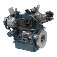
Valve Clearance
• Valve clearance must be checked and adjusted when engine
is cold.
1. Remove the cylinder head cover and the glow plugs.
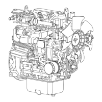
2. Align the “1TC” mark (1) on the flywheel and alignment mark (2)
on the rear end plate so that the No. 1 piston comes to the
compression top dead center.
3. Check the following valve clearance marked with “✩” using a
thickness gauge.
4. If the clearance is not within the factory specifications, adjust with
the adjusting screw.
5. Then turn the flywheel 6.28 rad (360 °), and align the “1TC” mark
(1) on the flywheel and alignment mark (2) on the rear end plate
so that the No. 1 piston comes to the overlap position.
6. Check the following valve clearance marked with “✩“ using a
feeler gauge.
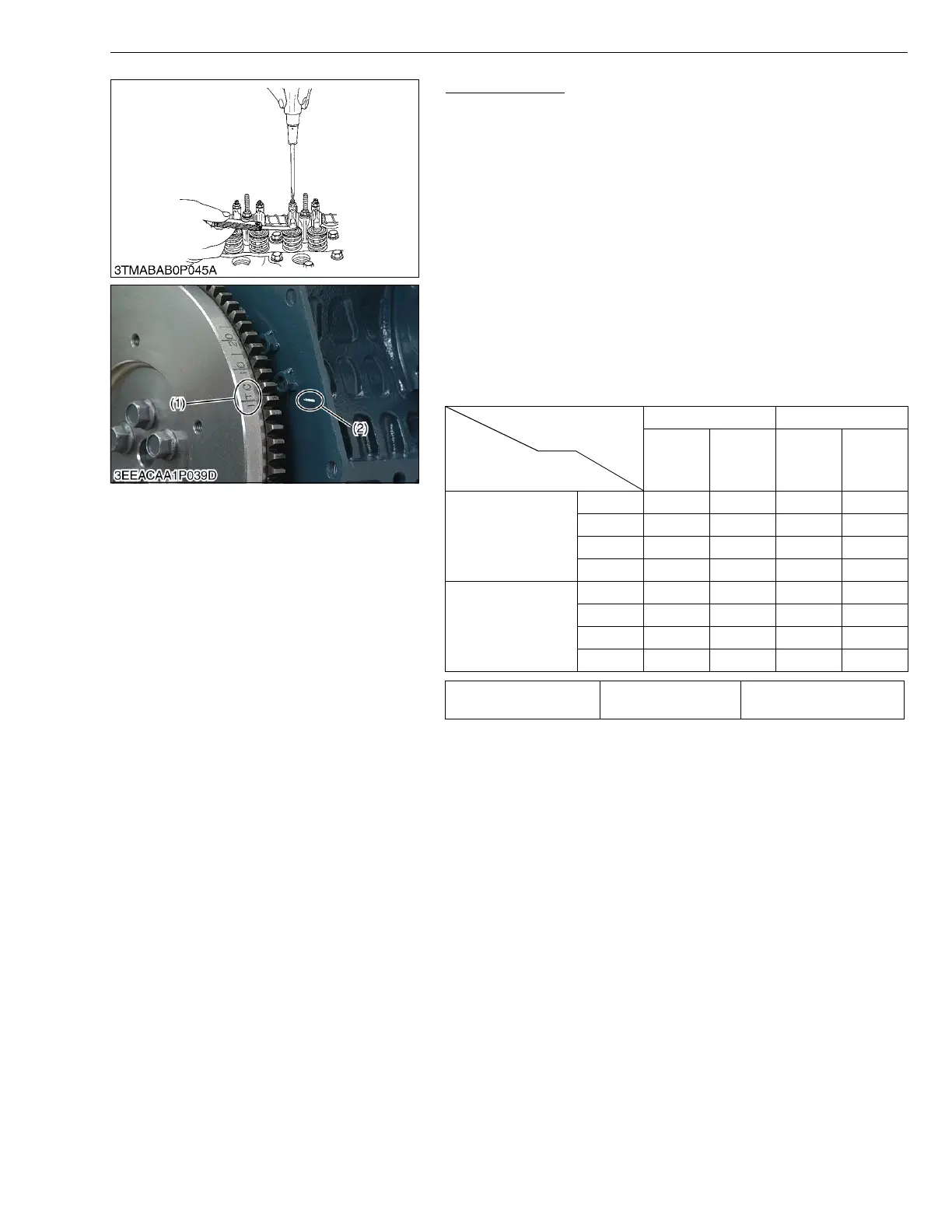
• The sequence of cylinder numbers is given as No. 1, No. 2,
No. 3 and No. 4 starting from the gear case side.
• After adjusting the valve clearance, secure the adjusting
screw with the lock nut.
W10155550
Number of cylinders
Valve arrangement
Adjustable cylinder
location of piston
3 cylinder 4 cylinder
IN. EX. IN. EX.
When No. 1 piston is
at compression top
dead center
1st ✩✩✩✩
2nd ✩✩
3rd ✩✩
4th
When No. 1 piston is
at overlap position
1st
2nd ✩✩
3rd ✩✩
4th ✩✩
Valve clearance Factory spec.
0.145 to 0.185 mm
0.00571 to 0.00728 in.
(1) “1TC” Mark (2) Alignment Mark
 Loading...