DIESEL
ENGINE
05
SERIES
WSM,
01640
[2]
OIL
PUMP
I
-
11900F10080
[3]
RELIEF
VALVE
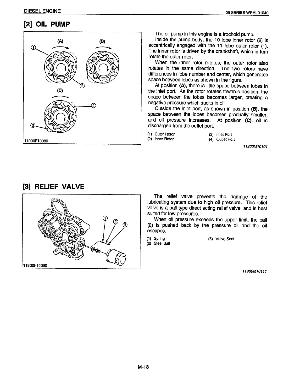
The oil pump in this engine is a trochoid pump.
Inside the pump body, the
10 lobe inner rotor (2) is
eccentrically engaged with the
11
lobe outer rotor
(1).
The inner rotor is driven by the crankshaft, which in turn
rotate the outer rotor.
When the inner rotor rotates, the outer rotor also
rotates in the same direction. The two rotors have
differences in lobe number and center, which generates
space between lobes as shown in the figure.
At position
(A),
there is little space between lobes in
the inlet port. As the rotor rotates towards position, the
space between the lobes becomes larger, creating a
negative pressure which sucks in oil.
Outside the inlet port, as shown in position
(B),
the
space between the lobes becomes gradually smaller,
and
oil
pressure increases. At position
(C),
oil is
discharged from the outlet port.
(1)
Outer
Rotor
(2)
Inner Rotor
(3)
Inlet
Port
(4)
Outlet
Port
119OOM10101
The relief valve prevents the damage of the
lubricating system due to high oil pressure. This relief
valve is a ball type direct acting relief valve, and is best
suited for low pressures.
When oil pressure exceeds the upper limit, the ball
(2)
is pushed back by the pressure oil and the oil
(1)
Spring
(3)
Valve Seat
(2) Steel Ball
11900F10090
119OOM10111
M-13
Redistribution or publication of this document,
by any means, is strictly prohibited.
 Loading...