DIESEL ENGINE
05
SERIES
WSM,
01640
d6
11900F10180
I
I//
I
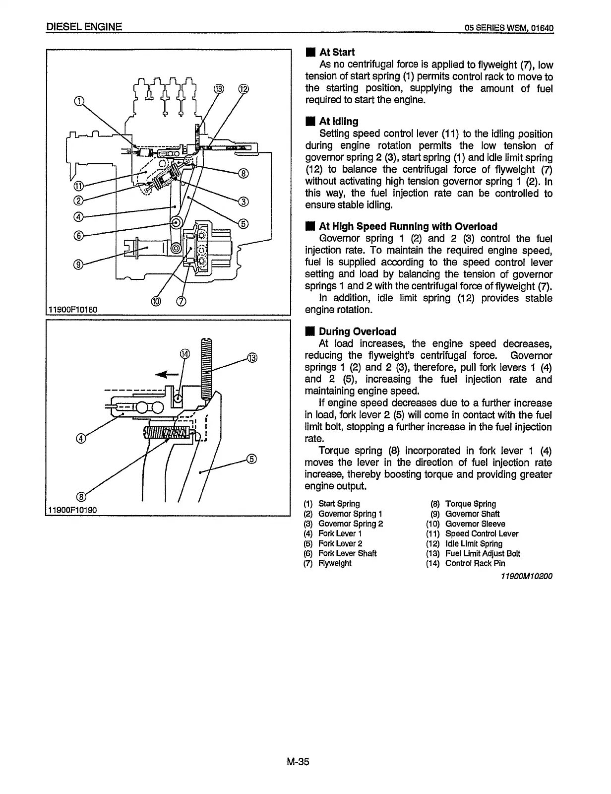
At Start
As
no centrifugal force is applied to flyweight
(7),
low
tension
of
start spring
(1)
permits control rack to move to
the starting position, supplying the amount of fuel
required to start the engine.
I
At Idling
Setting speed control lever (1 1) to the idling position
during engine rotation permits the low tension of
governor spring 2
(3),
start spring (1) and idle limit spring
(12) to balance the centrifugal force of flyweight
(7)
without activating high tension governor spring
1
(2). In
this way, the fuel injection rate can be controlled to
ensure stable idling.
I
At
High
Speed Running with Overload
Governor spring 1 (2) and
2
(3) control the fuel
injection rate.
To
maintain the required engine speed,
fuel is supplied according to the speed control lever
setting and load by balancing the tension
of
governor
springs
1
and
2
with the centrifugal force of flyweight
(7).
In addition, idle limit spring (12) provides stable
engine rotation.
I
During Overload
At load increases] the engine speed decreases,
reducing the flyweight’s centrifugal force. Governor
springs
1
(2)
and
2
(3), therefore, pull fork levers
1
(4)
and 2
(5),
increasing the fuel injection rate and
maintaining engine speed.
If
engine speed decreases due to a further increase
in load, fork lever
2
(5)
will
come in contact with the fuel
limit bolt, stopping a further increase in the fuel injection
rate.
Torque spring
(8) incorporated in fork lever 1 (4)
moves the lever in the direction of fuel injection rate
increase] thereby boosting torque and providing greater
engine output.
(1)
Start
Spring
(8)
Torque Spring
(2)
Governor Spring
1
(9)
Governor
Shaft
(3)
Governor Spring
2
(1
0)
Governor Sleeve
(4)
Fork Lever 1 (1
1)
Speed Control
Lever
(5)
Fork
Lever
2
(12) Idle
Llmlt
Spring
(6)
Fork Lever Shaft (13) Fuel
Limit
Adjust
Bolt
(7)
Flyweight
(14)
Control Rack Pin
11900M10200
M-35
Redistribution or publication of this document,
by any means, is strictly prohibited.
 Loading...