11
WG972-E2, DF972-E2, WSM
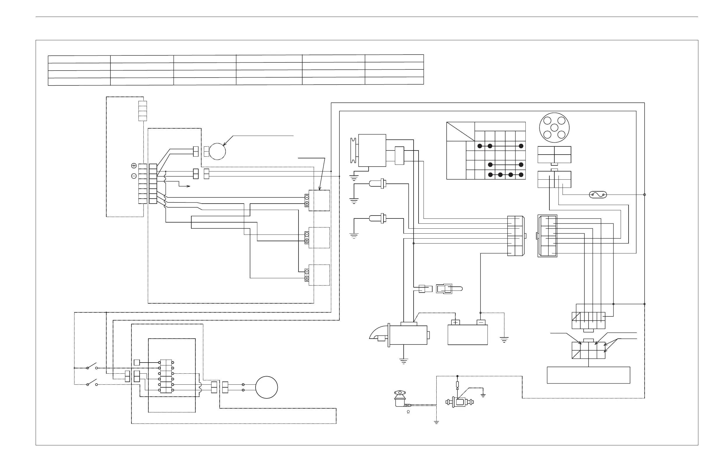
WIRING DIAGRAM
WIRING DIAGRAM
WIRE HARNESS (IGNITER)
B ........ Black BY ...... Black / Yellow GW ...... Green / White LW....... Blue / White R ....... Red Y ...... Yellow
BOr ......Black / Red Br ....... Brown Gr...... Gray Or ....... Orange RB ...... Red / Black YW ....... Yellow / White
BR ........Black / Red G ....... Green L....... Blue Pi ....... Pink RW ...... Red / White
BW ...... Black / White GY ..... Green / Yellow LB ...... Blue / Black Pu ...... Purple W ...... White
Color of Wiring
Igniter
Sensor Assy, Crank Position
Ignition Coil
Engine Speed Pulse Output
Sensor
IG 1
IG 3
IG 2
WIRE HARNESS (IGNITER)
Engine Speed Sensor
WIRE HARNESS (ELECTRONIC GOVERNOR)
Electronic Governor
Select Switch
Relay
Driver
Power Input
(Gasoline)
Solenoid
Valve
Cavbuleter
Fuel Pump
Pilot Box Assy
Starter Battery
Fuse
Charge
Lamp
Water Temp
Lamp
Oil (-)
Fuse
Starter Switch
50 30
19 AC
50 30
19 AC
17
30
19
50 AC
19 AC30 17 50
Terminal
Position
3
2
1
0
Alternator
Water Temp
Switch
Oil Switch
1
3
42
1
3
42
8
6
57
8
6
57
B
LE
IG
BR BYWB
BR BYWB
LRGW
LRGW
10 A
0.85
0.5 BY
0.5 G
0.5 B
3 R
2 BW
0.5 W
0.5 L
0.5 BY
0.5 G
0.5 B
3 R
2 BW
0.5 W
0.5 L
(12 V, 17.3 , 0.7 A)
(1.5 A, 12 V)
1
2
ER
12 V
OV
10
9
5
4
1
6
7
12
3
11
2
8
MPU +
+ 5 V
Aux 1 +
MPU -
Aux -
GND
12 P
-
-
+
+
+
+
12 V
A
J
K
L
I
H
F
G
E
J
K
L
I
H
F
G
E
D
C
B
Or
LB
WB
RB
Or
Or
Or
LB
WB
RB
B
R
B
R
G
L
1
2
1
2
1
2
1
2
AVX 0.75 f
5.5A, AVX 0.75 f
RW
3 R 3 R
AVX 2
AVX 3
2 R
3EBAAABZP002A