S-59
V3300-E2B, V3300-T-E2B, WSM
DIESEL ENGINE
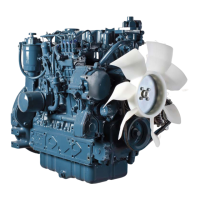
Clearance between Valve Stem and Valve Guide
1. Remove carbon from the valve guide section.
2. Measure the valve stem O.D. with an outside micrometer.
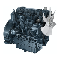
3. Measure the valve guide I.D. of the cylinder head at the most
wear part as shown in the figure below with a small hole gauge.
And calculate the clearance.
4. If the clearance exceeds the allowable limit, replace the valves.
If it still exceeds the allowable limit, replace the valve guide.
W1061883
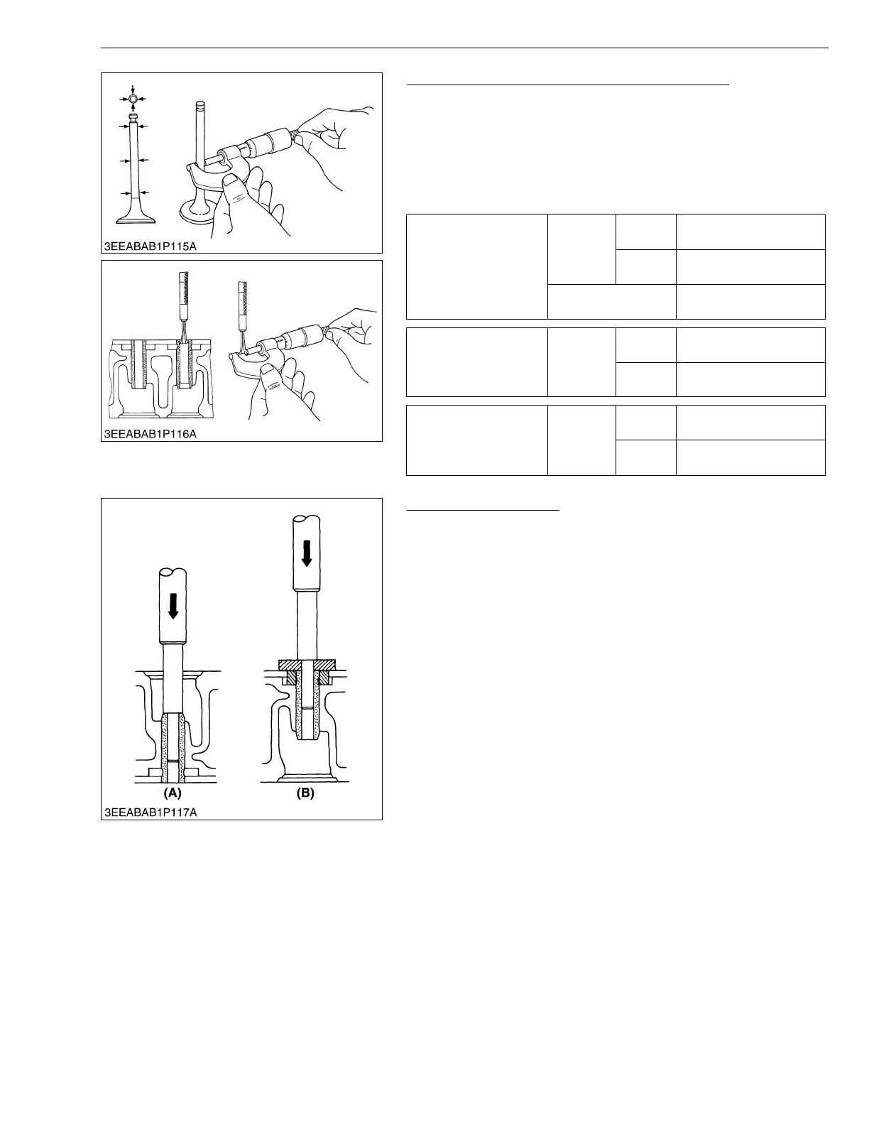
Replacing Valve Guide
(When removing)
1. Using a valve guide replacing tool, press out the used valve
guide.
(When installing)
1. Clean a new valve guide, and apply engine oil to it.
2. Using a valve guide replacing tool, press in a new valve guide
until it is flush with the cylinder head as shown in the figure.
3. Ream precisely the I.D. of the valve guide to the specified
dimension.
• Do not hit the valve guide with a hammer, etc. during
replacement.
W1062212
Clearance between
valve stem and guide
Factory
spec.
Intake
valve
0.055 to 0.085 mm
0.0022 to 0.0033 in.
Exhaust
valve
0.040 to 0.070 mm
0.0016 to 0.0028 in.
Allowable limit
0.1 mm
0.0039 in.
Valve stem O.D.
Factory
spec.
Intake
valve
6.960 to 6.975 mm
0.2740 to 0.2746 in.
Exhaust
valve
7.960 to 7.975 mm
0.3134 to 0.3140 in.
Valve guide I.D.
Factory
spec.
Intake
valve
7.030 to 7.045 mm
0.2768 to 0.2774 in.
Exhaust
valve
8.015 to 8.030 mm
0.3155 to 0.3161 in.
(A) When Removing (B) When Installing