S-33
V3300-E2B, V3300-T-E2B, WSM
DIESEL ENGINE
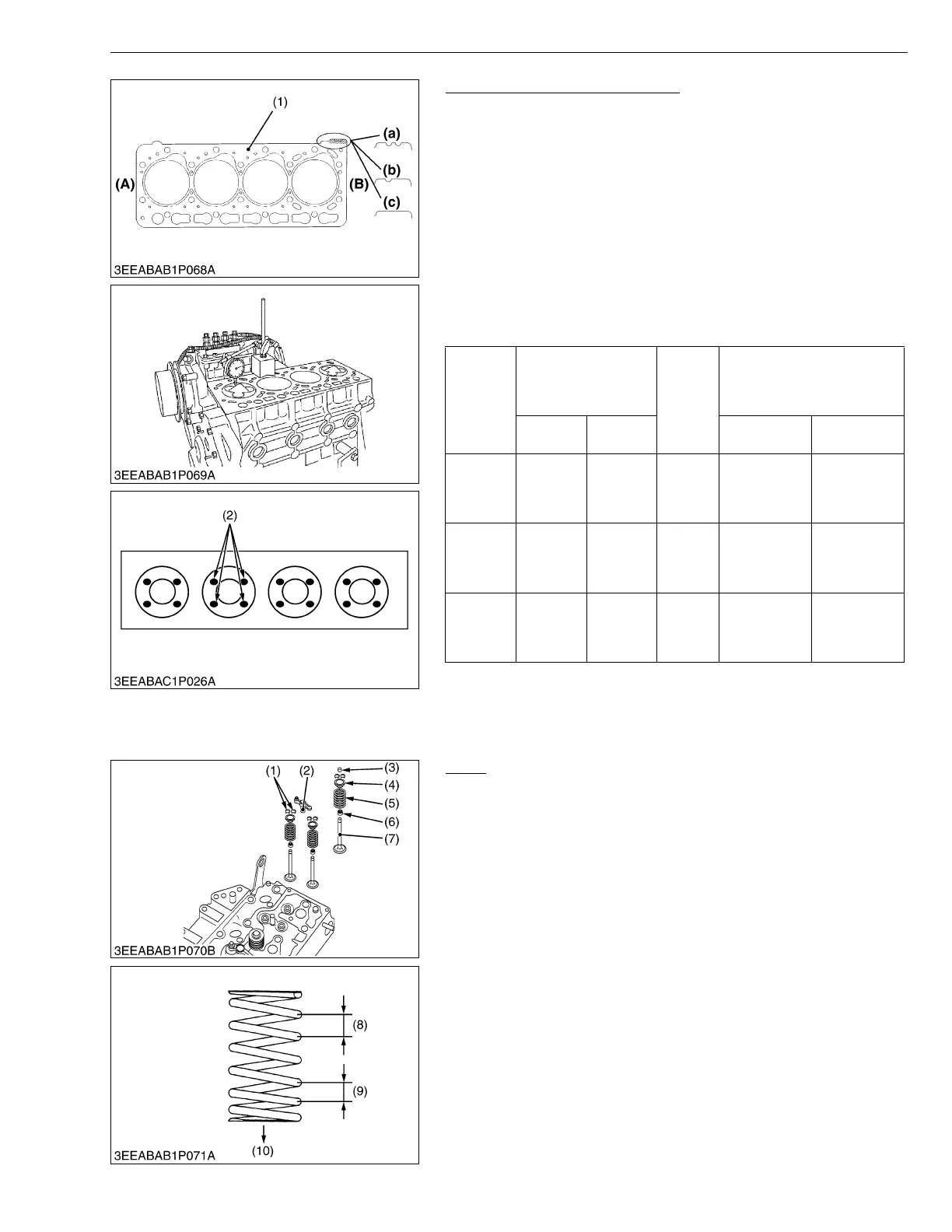
Selecting Cylinder Head Gasket
■ Replacing the Cylinder Head Gasket
1. Make sure the notch mark (a), (b) or (c) of cylinder head gasket
(1) in advance.
2. Replace the same notch mark (a), (b) or (c) as the original
cylinder head gasket (1).
■ Selecting the Cylinder Head Gasket
• Select the cylinder head gasket (1) thickness to meet with the top
clearance when replacing the piston, piston pin bush, connecting
rod or crankpin bearing.
1. Measure the piston head’s protrusion or recessing from the
crankcase cylinder face (4 spots per each piston and average of
four pistons) using the dial gauge as shown in figure.
2. Select the suitable cylinder head gasket refer to the table below.
W1022965
Valve
1. Remove the valve cap (3) and the valve spring collets (1)
compressing the valve spring (5) with the valve spring retainer
(4).
(When reassembling)
• Install the intake valve spring with its small-pitch end downward
(at the head side).
• Wash the valve stem and valve guide hole, and apply engine oil
sufficiently.
• After installing the valve spring collets, lightly tap the stem to
assure proper fit with a plastic hammer.
W1053044
Notch
Mark of
Cylinder
Head
Gasket
Thickness of cylinder
head gasket
Part
Code
Piston Head’s protrusion or
recessing from the level of
Crankcase cylinder face.
(average of 4 pistons)
Before
tightening
After
tightening
V3300-E2B V3300-T-E2B
2 notches
(a)
0.90 mm
0.0354 in.
0.80 mm
0.0315 in.
1C020-
03310
-0.07 to
+0.049 mm
-0.0028 to
+0.0019 in.
-0.27 to
-0.151mm
-0.0110 to
-0.0059 in.
1 notch (b)
1.00 mm
0.0394 in.
0.90 mm
0.0354 in.
1C020-
03600
+0.050 to
+0.149 mm
+0.0020 to
+0.0058 in.
-0.15 to
-0.051 mm
-0.0059 to
-0.0020 in.
Without
notch (c)
1.05 mm
0.0413 in.
0.95 mm
0.0374 in.
1C020-
03610
+0.150 to
+0.20 mm
+0.0059 to
+0.0078 in.
-0.05 to 0 mm
-0.0019 to 0 in.
(1) Cylinder Head Gasket
(2) Measuring Point
(A) Gear Case Side
(B) Flywheel Side
(a) 2 Notches
(b) 1 Notch
(c) Without Notch
(1) Valve Spring Collet
(2) Arm Bridge
(3) Valve Cap
(4) Valve spring Retainer
(5) Valve Spring
(6) Valve Stem Seal
(7) Valve
(8) Large Pitch
(9) Smaller Pitch
(10) Install the spring with its smaller-
pitch end downward (at the head
side)