ECM SYSTEM
WG1605-G-E3,WG1605-L-E3,WG1605-GL-E3, DM
1-124
DTC 336-Crank Input Signal Noise
• Hardware: Crankshaft Position sensor
• Enabling Conditions: Key On, Engine On
• Set Conditions: Electrical noise or irregular crank pattern detected causing more than 1 crank re-synchronization
events in less than 800 ms
• Corrective Action(s): Illuminate MIL and disable fuel adaptive learn function for the rest of the key cycle.
• Emissions related fault
• Possible Causes: CKP+ or CKP circuits in wrong connector terminal slot, improper CKP signal due to sensor air
gap too large, excessive metal on sensor tip, improper wiring, intermittent connection in sensor circuitry,
intermittent sensor internal problem
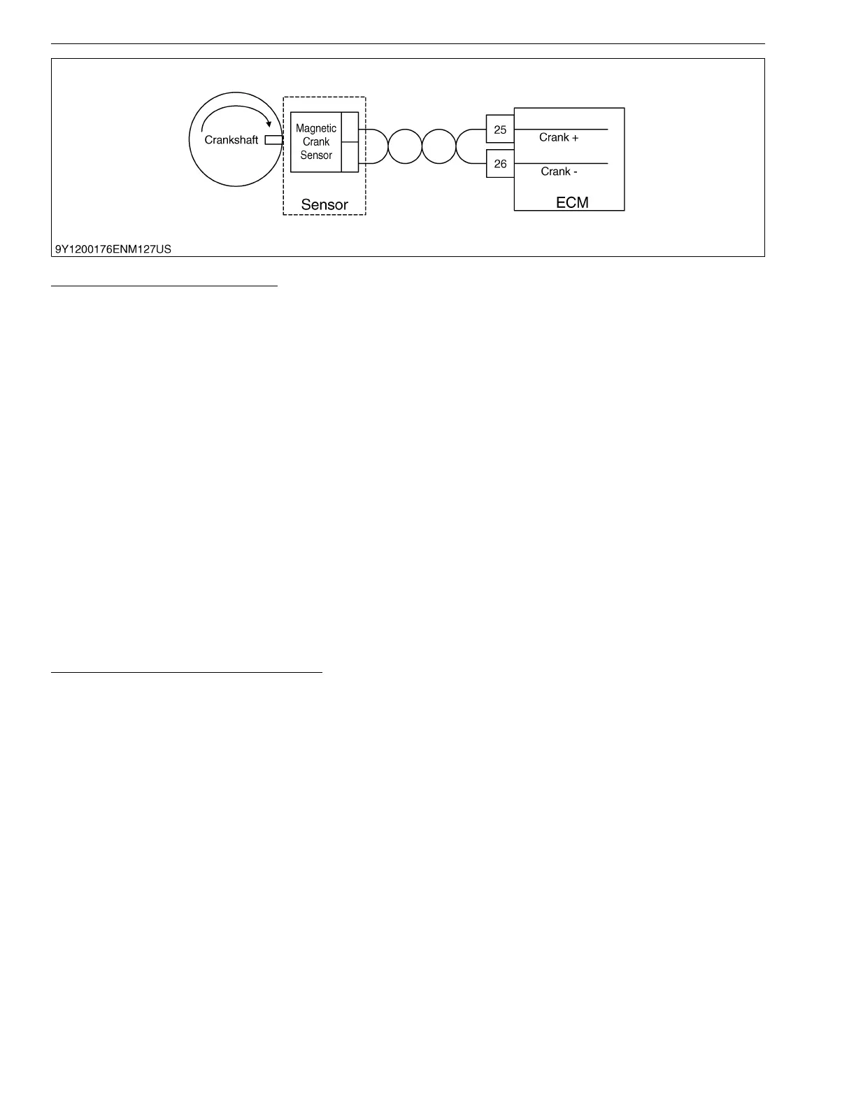
The crankshaft position sensor is a magnetic pick-up sensor installed in the engine block adjacent to a "coded"
trigger wheel located on the flywheel. The sensor-trigger wheel combination is used to determine crankshaft position
(with respect to TDC cylinder #1 compression) and the rotational engine speed. Determination of the crankshaft
position and speed is necessary to properly activate the ignition, fuel injection, and throttle governing systems for
precise engine control.
The ECM must see a valid crankshaft position signal while running. If no signal is present, the signal amplitude
is too high (due to improper air gap with respect to trigger wheel), or an irregular crank pattern is detected causing
the ECM to resynchronize × times for y ms or longer as defined in the diagnostic calibration (see set conditions
above), this fault will set. Irregular crank patterns can be detected by the ECM due to electrical noise, poor machining
of trigger wheel, or trigger wheel run out and/or gear lash.
Ensure crank circuit used with VR/magnetic pick-up sensors are properly twisted.
DTC 337-Loss of Crankshaft Input Signal
• Hardware: Crankshaft Position sensor
• Enabling Conditions: Key On, Engine On
• Set Conditions: Loss of crankshaft position signal (CKP) with more than 6 cam pulses from the camshaft position
sensor (CMP).
• Corrective Action(s): Illuminate MIL
• Emissions related fault
• Possible Causes: Loss of sensor feed, open sensor ground (5 Vrtn1 and CKP), open or shorted to ground signal
wire
The crankshaft position sensor is a magnetic pick-up sensor installed in the engine block adjacent to a "coded"
trigger wheel located on the flywheel. The sensor-trigger wheel combination is used to determine crankshaft position
(with respect to TDC cylinder #1 compression) and the rotational engine speed. Determination of the crankshaft
position and speed is necessary to properly activate the ignition, fuel injection, and throttle governing systems for
precise engine control.
The ECM must see a valid crankshaft position signal while running. The engine typically stalls or dies as a result
of this fault condition due to the lack of crankshaft speed input resulting in the inability to control ignition timing.

 Loading...