6. - Putting into service
HRB202-202S-252D-302D
41
KN136JGB_D
Power harrow
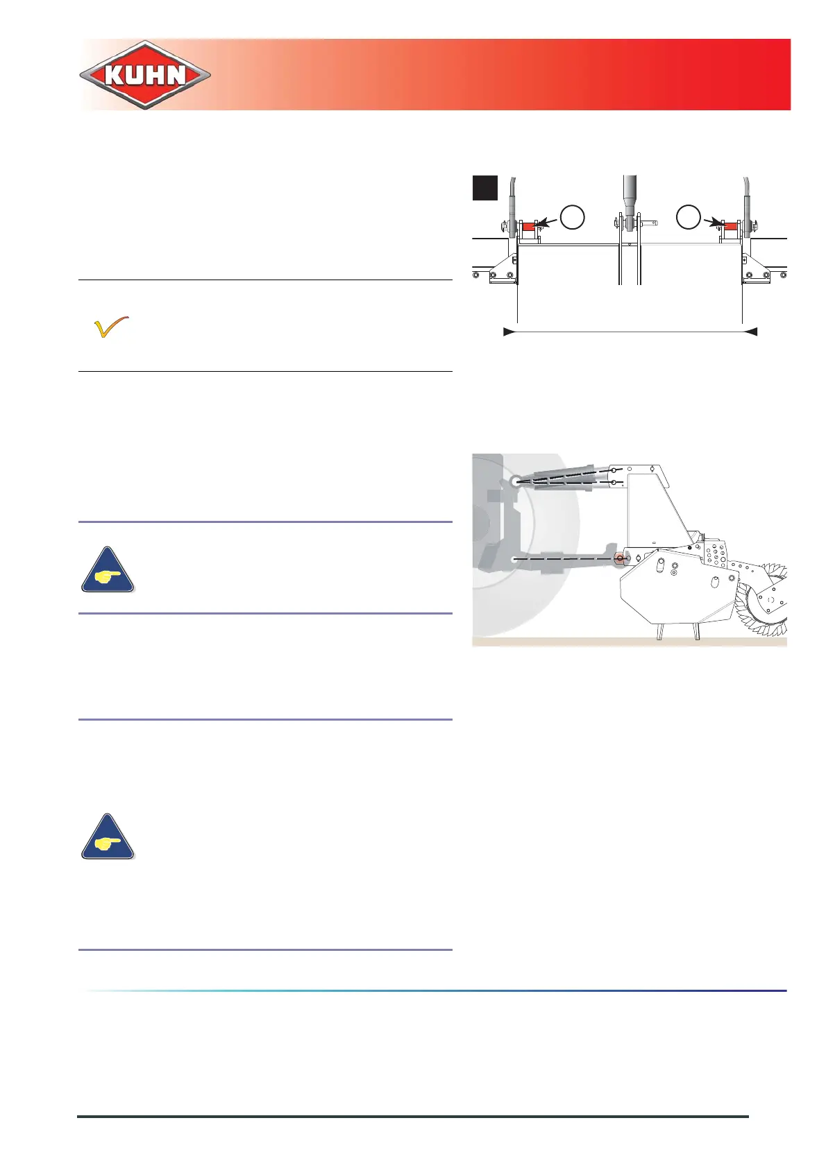
Category 3 linkage (c) (Position only to be used on
exceptional occasions):
• L= 965 mm (3’2’’).
- Position ball joints of tractor lower links in line with
holes of machine lower yokes.
Position the 2 bushes (1) on lower hitch pins
when the machine is coupled to a tractor fitted
with a standardized 3 point attachment category
2.
- Insert lower hitch pins and secure them with lynch
pins.
- Attach top link with hitch pin.
- Use tractor and machine attachment holes to
adjust the top link position.
To obtain optimum PTO shaft angles and
tractor lift capacity, the top link must be
parallel to the lower links or slightly pointing
downwards towards the tractor.
- Secure hitch pin with lynch pin.
- When optional equipment is used, follow
specific procedures mentioned in the
related section:
• Optional equipment / Hydraulic lift
linkage / Coupling device.
• Optional equipment / Rear attachment
with double acting hydraulic lift /
Coupling device.
• Optional equipment / Lights and
indicators / Coupling and uncoupling.
• Optional equipment / Front signalling
elements / Coupling and uncoupling.
c



 To Next Page