EasyManua.ls Logo

Kwikset 275 User Manual

Kwikset 275
4 pages
To Next Page IconTo Next Page
Page #1 background imageLoading...
Page #1 background image
door frame
Make sure hole in door frame is drilled a
minimum of 1” (25 mm) deep.
Required tools
Ruler4 AA Batteries
Hammer
Wood
block
Pliers
Phillips screwdriver
Additional Tools (depending on application)
If drilling a new door, use the supplied template and the complete
door drilling instructions available at www.kwikset.com/doorprep
Note: Additional door preparation may be
required for doors with 11/2" (38 mm) holes.
Consult the deadbolt drilling instructions at
www.kwikset.com/doorprep
or
backset
Measure to conirm that the hole in
the door is either 21/8" (54 mm) or
11/2" (38 mm).
Measure to conirm that the backset is
either 23/8" or 23/4" (60 or 70 mm).
23/8" or 23/4"
60 or 70 mm
13/8"– 13/4"
35 mm or 44 mm
Measure to conirm that the hole in
the door edge is 1" (25 mm).
Measure to conirm that the
door is either 13/8" or 13/4"
(35 mm or 44 mm) thick.
A
A B C
D
B C D
21/8"
54 mm
11/2"
38 mm
1"
25 mm
1
Prepare the door and check dimensions
2
Install the latch and strike
Latch
Exterior Assembly
Interior Cover
Strike Cylinder
A
E
J K L M
F G H
B C D
Parts in the box
Drive-In Collar
Keys
Latch and
Strike Screws
Mounting Plate
Interior Assembly
Screws
Interior
Assembly
Mounting Plate
Screws
Align tabs with
holes in collar.
A
A
A
K (2x)
K (2x)
B
180°
Is the door edge chiseled?
Is the slotted hole centered in the door hole?
Hold the latch in front of the door hole, with
the latch face lush against the door edge.
YES
YES
NO
NO
Install latch in door with
supplied screws.
No adjustment is
required. Proceed
to next step.
slotted hole
is centered
slotted hole is
NOT centered
Rotate latch face as
shown to extend latch.
Remove rectangular
face from latch and
install drive-in collar.
Install latch in door with
wood block and hammer.
Install strike on the door frame.
Make sure the latch bolt is fully retracted (in the
unlocked position).
or
chiseled
not
chiseled
or
Make sure
slotted hole is at
bottom of latch.
Make sure
slotted hole is at
bottom of latch.
Ensure collar
snaps into place.
Pull collar to test
for tight it.
unlocked
C
A
1 / 4
ENGLISH
66877001
Rev 01
Installation and User Guide
Kwikset
Technical Support
1-800-327-5625
www.kwikset.com
275 Touchscreen
Electronic Deadbolt
Question and Answer IconNeed help?

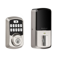
Do you have a question about the Kwikset 275 and is the answer not in the manual?

Kwikset 275 Specifications

General IconGeneral
BrandKwikset
Model275
Keyless EntryNo
KeywayKW1
Adjustable BacksetYes
Door Thickness1-3/8" to 1-3/4"
Adjustable LatchYes
Reversible HandingYes
Backset2-3/8" or 2-3/4"

Summary

Prepare the door and check dimensions

Door Hole Diameter Measurement

Measure the door hole diameter to ensure it is 2-1/8" (54 mm) or 1-1/2" (38 mm).

Backset Measurement

Confirm the backset measurement is 2-3/8" or 2-3/4" (60 or 70 mm).

Door Edge Hole Diameter

Measure the door edge hole to confirm it is 1" (25 mm).

Door Thickness Measurement

Measure the door thickness to ensure it is 1-3/8" or 1-3/4" (35 mm or 44 mm).

Install the latch and strike

Latch Placement and Alignment

Hold the latch flush against the door edge and check slot centering.

Chiseled Door Edge Installation

Install the latch based on whether the door edge is chiseled or not.

Strike Installation on Door Frame

Install the strike plate on the door frame, ensuring proper depth.

Prepare keypad and mounting plate

Door Diameter Adjustment

Adjust the mounting plate for smaller door hole diameters (1-1/2" or 38 mm).

Install exterior assembly

Cylinder and Cable Routing

Install the cylinder and route the cable through the mounting plate.

Torque Blade Orientation

Ensure the torque blade is horizontal before insertion.

Latch Operation Test

Test the latch for smooth operation after installation.

Securing the Mounting Plate

Secure the mounting plate using the supplied screws.

Install interior assembly

Battery Installation and Reset

Load batteries and press the reset button to initiate setup.

Connector Alignment and Turnpiece Rotation

Align connectors, ensure tight cable connection, and rotate turnpiece away from door edge.

Interior Assembly Securing

Secure the interior assembly with screws and reinstall the battery cover.

Enter door handing code and test lock

Activate Screen and Enter Handing Code

Touch the screen to activate and enter the handing code for door orientation.

Lock and Unlock Test

Test the lock and unlock functionality using the Lock symbol and default User Code.

Programming

Change Programming Code

Instructions to change the existing Programming Code.

Add User Codes

Steps to add new User Codes to the lock.

Delete Individual User Codes

How to remove specific User Codes from the lock.

Delete All User Codes

Procedure to erase all programmed User Codes.

Enable/Disable User Codes

How to temporarily disable User Code access.

Change Auto-Lock Time Delay

Adjust the automatic re-locking time delay.

Restore Default Settings

Reset the lock to its factory default configuration.

Troubleshooting

Turnpiece Operation Issues

Solutions for when the turnpiece cannot rotate or operate the lock.

Touchscreen Unresponsiveness

Troubleshooting steps for a touchscreen that does not respond.

Lock/Unlock Failures

How to address issues where the lock cannot be locked or unlocked by the touchscreen.

Latch Bolt Extension Error

Troubleshooting for when the latch bolt extends and retracts incorrectly.

User Code Unlock Failure

Steps if the User Code fails to unlock the door.

Locking Error Beeps

Addresses lock beeping 3 times when trying to lock the door.

Related product manuals