2JL/2JJ/2JG/2JD
1-5-10
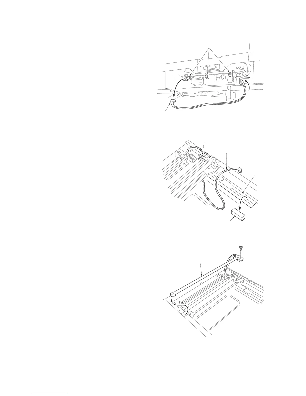
11. Remove one connector of the inverter PWB.
12. Release the wire from the wire saddle and
pull the connector out from the opening on
the rear of the scanner unit.
Figure 1-5-22
13. Remove the sponge from the wire guide and
release the wire.
14. Move the mirror 1 frame to notch position
and release the wire from the wire holder.
Figure 1-5-23
15. Remove one screw and remove the expo-
sure lamp.
16. Replace the exposure lamp and then install
the lamp.
17. Refit the contact glass, scanner right and left
covers, upper left cover, front left cover 1,
clip support and rear cover.
Figure 1-5-24
Wire saddles
Connector
Opening
Sponge
Wire guide
Wire
Wire holder
Exposure lamp
 Loading...