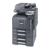
2PZ-3
1-5-31
(3) Detaching and refitting the main PWB
Procedure
1. Remove the FAX control PWB, if
installed (see page 1-5-40).
2. Remove the right rear cover, right cover
and right lower cover (see page 1-5-6).
3. Remove the cap of the network
connector.
Figure 1-5-44
4. Remove four screws and then remove
the power source shield.
*: When the power source shield is reat-
tached, each screw of two types (A and
B) should be secured at the original posi-
tion.
Figure 1-5-45
Cap
Network
connector
Power source shield
Screw B
Screws A
Screw A
 Loading...
