EasyManua.ls Logo

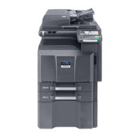
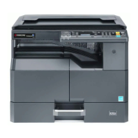
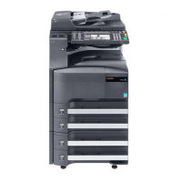
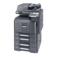
Kyocera TASKalfa 520i Service Manual

Kyocera TASKalfa 520i
508 pages
To Next Page IconTo Next Page
Page #1 background imageLoading...
Page #1 background image
SERVICE
MANUAL
Published in May 2010
842KS113
2KSSM063
Rev. 3
TASKalfa 420i
TASKalfa 520i

Table of Contents

Questions and Answers:

Kyocera TASKalfa 520i Specifications

General IconGeneral
FunctionPrint, Copy, Scan, Fax
Print Speed (Black)52 ppm
Print Resolution1200 x 1200 dpi
Standard Paper Capacity1, 150 sheets
Scan Resolution600 x 600 dpi
Fax Modem Speed33.6 Kbps
ConnectivityUSB, Ethernet, Wi-Fi
Operating System CompatibilityWindows, macOS, Linux
TypeAll-in-One Printer
Memory (Standard)2 GB
Max Print Resolution1200 x 1200 dpi
Duplex PrintingStandard

Summary

Safety Precautions

Symbols

Indicates warnings, dangers, and cautions, with specific points of attention shown inside the symbol.

1.Installation Precautions

2.Precautions for Maintenance

3.Miscellaneous

1-1 Specifications

1-1-1 Specifications

Details machine specifications like type, printing method, supported original types, paper weight, and size.

1-1-2 Parts names

Identifies and labels major machine parts using figures and numbers.

1-1-3 Machine cross section

Provides a cross-sectional view of the machine, illustrating the paper path and internal components.

1-2 Installation

1-2-1 Installation environment

Specifies environmental requirements, location, and installation dimensions for the machine.

1-2-2 Unpacking and installation

Outlines the step-by-step procedure for unpacking the machine and completing the initial setup.

1-2-3 Installing the key counter (option)

Details the components and procedure required for installing the optional key counter system.

1-2-4 Replacing the expanded memory

Provides instructions for safely removing and installing expanded memory modules within the machine.

1-3 Maintenance Mode

1-3-1 Maintenance mode

Explains how to enter and execute various maintenance items for servicing the machine.

1-3-2 Management mode

Describes the management functions accessible by users for changing settings like default configurations.

1-3-3 Maintenance modes item list

Lists all available maintenance mode items, their numbers, content, and initial settings.

1-4 Troubleshooting

1-4-1 Paper misfeed detection

Details paper misfeed indications, causes, and corrective measures for various locations.

1-4-2 Self-diagnosis

Explains the self-diagnostic function and lists system errors with their causes and corrective actions.

1-4-3 Image formation problems

Illustrates common image quality issues like light image, dark image, or blurred image with potential causes.

1-4-4 Electric problems

Lists electrical issues, their causes, and troubleshooting steps for components like motors and power supply.

1-4-5 Mechanical problems

Covers mechanical issues such as paper feed problems, worn rollers, and misaligned parts.

1-4-6 Send error code

Lists error codes for sending functions like Scan to SMB, FTP, and E-mail, with causes and solutions.

1-5 Assembly and Disassembly

1-5-1 Precautions for assembly and disassembly

Outlines critical safety warnings and precautions to be followed before starting disassembly or reassembly.

1-5-2 Paper feed section

Details the procedure for detaching and refitting pulleys and cleaners in the paper feed section.

1-5-3 Optical section

Explains the process for detaching and refitting components within the optical section, such as the exposure lamp.

1-5-4 Drum section

Provides instructions for detaching and refitting the drum unit and main charger unit.

1-5-5 Developing section

Details the procedure for detaching and refitting the developing unit and toner replenishment.

1-5-6 Transfer section

Explains how to detach and refit the transfer roller unit and clear counter values.

1-5-7 Fuser section

Covers procedures for detaching and refitting fuser unit components like heaters, thermistors, and rollers.

1-5-8 Others

Details replacement procedures for components like ozone filters, dust filters, and the hard disk.

1-6 Requirements on PWB Replacement

1-6-1 Upgrading the firmware

Describes the procedure for upgrading the machine's firmware using a USB memory.

1-6-2 Adjustment-free variable resistors (VR)

Lists the adjustment-free variable resistors (VR) that are factory set and cannot be adjusted in the field.

1-6-3 Remarks on main PWB replacement

Provides remarks for main PWB replacement, including EEPROM transfer.

1-6-4 Remarks on engine PWB replacement

Offers remarks for engine PWB replacement, emphasizing EEPROM transfer.

2-1 Mechanical construction

2-1-1 Paper feed section

Explains the paper feed mechanism, including cassette and MP tray paper feed subsections.

2-1-2 Optical section

Describes the optical section, covering the scanner, mirror frame, and image scanner unit.

2-1-3 Drum section

Details the drum section components like the drum, main charger unit, and cleaning section.

2-1-4 Developing section

Explains the developing section, including the developing unit and toner container for replenishment.

2-1-5 Transfer and separation sections

Covers the transfer roller, separation electrode, and drum separation claws for paper transfer and separation.

2-1-6 Fuser section

Details the fuser section components like heat roller, press roller, and fuser heaters for fusing toner.

2-1-7 Eject and switchback sections

Explains the eject and switchback sections responsible for paper ejection and transfer path switching.

2-1-8 Duplex section

Describes the duplex section, where paper is reversed for duplex copying.

2-2 Electrical Parts Layout

2-2-1 Electrical parts layout

Lists the electrical parts layout, including PWBs, switches, sensors, motors, and other components.

2-3 Operation of the PWBs

2-3-1 Power source PWB

Explains the function of the power source PWB in generating voltages and controlling fuser heaters.

2-3-2 Engine PWB

Describes the engine PWB's role in controlling other PWBs and machine components.

2-3-3 Main PWB

Details the main PWB's functions in controlling image processing and the operation panel.

2-3-4 ISM PWB

Explains the ISM PWB's role in controlling the scanner section.

2-3-5 Main operation PWB

Describes the main operation PWB's functions in controlling the touch panel and LCD indication.

2-4 Appendixes

Maintenance parts list

Lists all maintenance parts with their service manual names, part numbers, and alternative part numbers.

Maintenance kits

Lists available maintenance kits, their part numbers, and alternative part numbers.

Periodic maintenance procedures

Outlines periodic maintenance tasks, user calls, 500K checks, points, cautions, and page references.

Chart of image adjustment procedures

Provides a chart detailing image adjustment procedures, including items, descriptions, and modes.

Wiring diagram No.1

Illustrates the electrical connections between various components using Wiring Diagram No.1.

Wiring diagram No.2

Illustrates the electrical connections between various components using Wiring Diagram No.2.

Wiring diagram No.3

Illustrates the electrical connections between various components using Wiring Diagram No.3.

Wiring diagram No.4

Illustrates the electrical connections between various components using Wiring Diagram No.4.

Wiring diagram No.5

Illustrates the electrical connections between various components using Wiring Diagram No.5.

Related product manuals