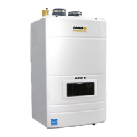
LAARS Heating Systems
Page 40
4.14 Plumbing Guidelines
Customer Service and Product Support: 800.900.9276 • Fax 800.559.1583
Headquarters: 20 Industrial Way, Rochester, NH, USA 03867 • 603.335.6300 • Fax 603.335.3355
1869 Sismet Road, Mississauga, Ontario, Canada L4W 1W8 • 905.238.0100 • Fax 905.366.0130
www.Laars.com Litho in U.S.A. © Laars Heating Systems 1607 Document 4296B
800.900.9276 • Fax 800.559.1583 (Customer Service, Service Advisors)
20 Industrial Way, Rochester, NH 03867 • 603.335.6300 • Fax 603.335.3355 (Applications Engineering)
1869 Sismet Road, Mississauga, Ontario, Canada L4W 1W8 • 905.238.0100 • Fax 905.366.0130
www.Laars.com
Document 4296B
Mascot FT, Heating Only, Gas Conversion Kit
pg 4 of 4
Figure E (Conversion label)
14.
Setup your combustion analyser and place the sensor into the combustion test port
15.
Per Table B for Max Fire
,
change dip switch 6 to ON and 7 to OFF. The unit will cycle up to MAX fi re.
16.
WAIT for your combustion analyser to stabilize. This may take up to 3 minutes depending on your
combustion analyser. Then measure the CO
2
for MAX fi re. Refer to Table C for acceptable MAX fi re
combustion readings Do NOT adjust CO2 at MAX Fire. ONLY in MIN Fire, so...
17.
Per Table B for MIN Fire
,
change dip switch 6 to OFF and 7 to ON. The unit will cycle down to MIN Fire.
18.
WAIT for your combustion analyser to stabilize. Then measure the CO
2
for MIN fi re. Refer to Table D for
acceptable MIN fi re combustion readings
19.
Open the Gas Valve Adjustment Port by removing the cap screw with a 4mm Allen wrench.
20.
Then use the 4 mm Allen wrench to make a minor adjustment (1/8 turn) to either increase or decrease CO
2
.
21.
It may be necessary to go back and forth between HI Fire and LOW Fire several times (and making
adjustments only at LOW Fire), before CO
2
at both are within acceptable levels. Be sure to put the
adjustment port cap screw back onto the valve when done.
22.
Once the CO
2
and manifold pressure measurements for both MIN and MAX Fire are acceptable per Table
C, set DIP switches 6 and 7 to the OFF position for Nominal Fire (normal operation).
23.
Write in the correct conversion date and the technicians name to the included gas conversion sticker. See
Figure E. Then apply that sticker adjacent to the rating plate.
24.
Put the boiler cover back on and assemble/tighten the 4 screws that hold the cover in place.
This unit was converted on ____/____/___to _____gas
with kit #____________by______________________
(name and company __________________________
accountable)_________________________________
___________________________________________
Cette unité a été converti ____/____/____ten ______gaz
en utilisant le kit numéro _____ par______________
(nom et société_________________________________
responsable)___________________________________
_____________________________________________
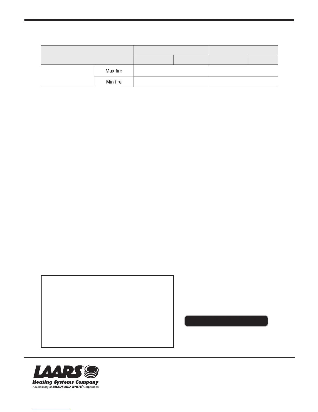
Manifold pressure Propane Gas (LP) Natural Gas (NG)
MFTHW 80/100
-0.102
˝
WC -0.102
˝
WC
0.00
˝
WC 0.00
˝
WC
MFTHW 120/140
-0.216
˝
WC -0.216
˝
WC
0.00
˝
WC 0.00
˝
WC
MFTHW 175
-0.169
˝
WC -0.129
˝
WC
-0.015
˝
WC -0.015
˝
WC
MFTHW 199
-0.173WC -0.134
˝
WC
-0.015
˝
WC -0.015
˝
WC
CO
2
value
Propane Gas (LP) Natural Gas (NG)
2˝ VENT 3˝ VENT 2˝ VENT 3˝ VENT
MFTHW 80/100
120/140/175/199
9.5~11% 8.5~10.5%
9~10.5 % 8~10%
Refer to the below table.
Table D
All sizes
4.13 Natural Gas to Propane Conversion (continued)