Do you have a question about the Label ETERNA 90 and is the answer not in the manual?
Details installer responsibilities, site stability, child safety, and proper product usage.
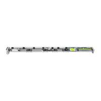
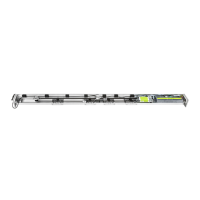
Introduces ETERNA 90D (double leaf) and ETERNA 90S (single leaf) automation models.
Lists power, speed, weight limits, temperature range, protection class, and dimensions.
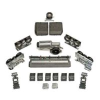
Illustrates components like control unit, motor, belt, pulleys, and casing with numbered labels.
Shows layout for double/single leaf doors, with/without electric locks, and calculation legends.
Details using fall prevention cables and screws to fasten and detach the casing.
Procedure to adjust drive belt tension using specific screws on the pulley assembly.
Guidance on setting the mechanical limit switch for correct door stopping points.
How to attach leaves to carriages, adjust height, and ensure proper horizontal alignment.
Precise measurements for mounting the transom to a wall or support structure.
Lists essential tools required for the installation process.
Details FAIL SAFE, FAIL SECURE, and BISTABLE electric locks and power failure behavior.
How to mount the electric lock and connect it to the ET-LOGIC-B control unit.
Shows connections for internal/external sensors, buttons, and programmer.
Details wiring for safety sensors, programmer, motor, battery, and electric locks.
Wiring instructions for connecting the ET-DSEL programmer to the control unit.
Lists crucial pre-startup checks like rail cleanliness, belt tension, and alignment.
Details how the programmer detects and communicates with the automation's control unit.
How to select the automation model and electric lock type during initial setup.
Configuration options for battery presence and safety sensor installation status.
Verifying door movement, sensor operation, and electric lock functionality.
Checking the status of all operator inputs via the ET-DSEL programmer.
Illustrated steps for mounting the battery containment plate and unit.
Details how to enable the stand-by mode using function F10.
Wiring and DIP switch settings for OA-AXIS T/OA-FLEX T safety sensors.
Wiring and DIP switch settings for the OAM-DUAL T safety sensor.
Description of the 5-position mechanical key selector and its modes.
Using the digital programmer to select operating modes and view system status.
Navigating through Set-Up, Functions, Selector Options, Language, and Service sections.
Setting function status (ON/OFF) for various automation features.
Adjusting operational parameters like opening speed and thrust power.
Allows choosing the display language for the programmer interface.
Explains technical, primary, and temporary password types and their usage.
Enables selection of specific operating modes to be shown on the programmer's display.
Accessing information like serial number, partial and total cycle counts.
Details how to view stored error messages and warnings.
Procedures for clearing event memory and partial cycle counters.
Describes factory configuration of functions and parameters before site installation.
Details functions like LOCK, GONG, AIR BLADE, BATTERY STATUS, DOOR STATUS, ALARM, MAINTENANCE.
Guides on connecting the buzzer and setting function F41m/F45m option B.
Steps for coupling the receiver and saving radio-control transmitters.
Procedure to erase all saved transmitter codes from the receiver's memory.
Details setting F52 to ON for forcible slow door closure after device activation.
Illustrates wiring between control units using UR24 modules for interlock.
Using a switch to bypass interlock and enable independent door operation.
Lists buzzer signals (beeps, sounds) and their corresponding meanings.
Recommends periodic maintenance operations and setting maintenance reminders.
Lists applicable harmonised European directives for safety and EMC compliance.
| Brand | Label |
|---|---|
| Model | ETERNA 90 |
| Category | Garage Door Opener |
| Language | English |