33
17) SAFETY SENSORS
This paragraph describes the procedure to be followed to properly connect and set-up some of the safety sensors available on the market and
complying with the EN12978 standard, to ensure a safety level which complies with PL=c - Cat. 2, as provided for by the EN16005 standard.
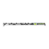
17.1) OA-AXIS T / OA-FLEX T SENSOR
OA-FLEX T / OA-AXIS T SENSOR WIRING ETERNA 90 OPERATOR ET-LOGIC-B TERMINAL
Correspondence between the sensor cables and the terminal board of the ET-LOGIC-B control unit
1. WHITE (+) Power supply TERMINAL 22 (+)
2. BROWN (-) Power supply TERMINAL 21 (-)
3. GREEN N.A. (activation) TERMINAL 12 (Internal radar) or 13 (External radar)
4. YELLOW COM TERMINAL 10 COMMON
5. PINK + Opto NPN (sensor 1 safety) TERMINAL 5 E.C.1 Closing safety sensor 1
PINK + Opto NPN (sensor 2 safety) TERMINAL 6 E.C.2 Closing safety sensor 2
6. BLUE - COM (sensor 1 safety) TERMINAL 7 COMMON
BLUE - COM (sensor 2 safety) TERMINAL 7 COMMON
7. RED (+) Test
TERMINAL 20 TEST (+)
8. BLACK (-) Test TERMINAL 21 (-)
OA-AXIS T / OA-FLEX T DIP SWITCH SETTINGS
DIP 10 = OFF Self-testing enabled
DIP 11 = OFF Output High
DIP 12 = ON Test input Low
For information about the adjustments and the other sensor
functional settings, please refer to the instructions supplied with
the OA-AXIS T sensor.
ET-DSEL PROGRAMMER FUNCTIONAL SETTINGS
F12 (S05) = ON If the safety sensor is installed on E.C.1
F13 (S06) = ON If the safety sensor is installed on E.C.2
F16 (S09) = ON Closing safety sensor test enabled
F18 (S11) = OFF LOW level test
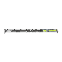
17.2) OAM-DUAL T SENSOR
OAM-DUAL T SENSOR WIRING ETERNA 90 OPERATOR ET-LOGIC-B TERMINAL
Correspondence between the sensor cables and the terminal board of the ET-LOGIC-B control unit
1. WHITE (+) Power supply TERMINAL 22 (+)
2. BROWN (-) Power supply TERMINAL 21 (-)
3. GREEN N.A. (activation) TERMINAL 12 (Internal radar) or 13 (External radar)
4. YELLOW COM TERMINAL 10 COMMON
5. PINK + Opto NPN (sensor 1 safety) TERMINAL 5 E.C.1 Closing safety sensor 1
PINK + Opto NPN (sensor 2 safety) TERMINAL 6 E.C.2 Closing safety sensor 2
6. BLUE - COM (sensor 1 safety) TERMINAL 7 COMMON
BLUE - COM (sensor 2 safety) TERMINAL 7 COMMON
7. RED (+) Test
TERMINAL 20 TEST (+)
8. BLACK (-) Test TERMINAL 21 (-)
OAM-DUAL T DIP SWITCH SETTINGS
DIP 7 = OFF Output High
DIP 8 = ON Test input Low
DIP 14 = OFF Self-monitoring enabled
For information about the adjustments and the other sensor
functional settings, please refer to the instructions supplied
with the OAM-DUAL T sensor.
ET-DSEL PROGRAMMER FUNCTIONAL SETTINGS
F12 (S05) = ON If the safety sensor is installed on E.C.1
F13 (S06) = ON If the safety sensor is installed on E.C.2
F16 (S09) = ON Closing safety sensor test enabled
F18 (S11) = OFF LOW level test
Application as activation and closing safety sensor
Application as activation and closing safety sensor