31
UK
TECHNICAL FEATURES
M
PRESSURE CURVES
PRESSURE CURVES/GAS DELIVERY
M
PRESSURE CURVES: The pressure curves indicate the output in kW according to the
backpressure in the combustion chamber, in mbars.
PRESSURE CURVES/GAS DELIVERY: These curves show the gas pressure, in milli-
bars, (at points Pi and Pt along the gas train) necessary to produce a given
delivery in m 3/h. The pressures have been measured with the burner working and with
a pressure of 0 mbar in the combustion
chamber. If the chamber is pressurized, the gas pressure necessary will be that given
in the diagram plus that in the combustion chamber.
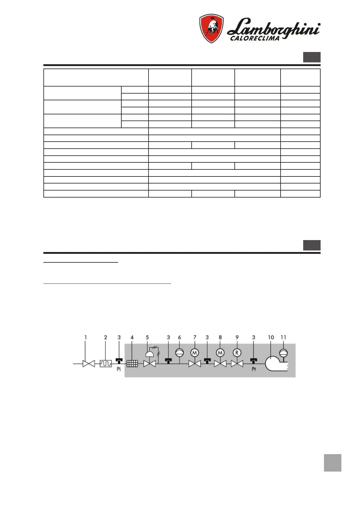
Legend
1 Interception cock - airtight at 1 bar and pressu-
re loss
0,5 mbar.
2 Vibration-damping joint
3 Gas pressure point for pressure reading
4 Gas lter
5 Gas pressure regulator
6 Minimum gas pressure control device (pressu-
re switch)
7 Class A solenoid safety valve. Closure time Tc
≤ 1”.
8 Class A solenoid safety valve. Closure time Tc ≤ 1”.
Ignition power between 10% and 40% of rated ther-
mal
power.
9 Gas delivery regulator, normally incorporated in ei-
ther solenoid valve 7 or 8.
10 Combustion head.
11 Minimum air pressure control device (pressure
switch)
BASIC GAS TRAIN
Model EM 3-E EM 6-E EM 9-E
Methane delivery
min 1,2 2,7 4,3 m
3
/h
max 3,8 6,7 9,0 m
3
/h
B/P delivery
min 0,4 1,0 1,5 m
3
/h
max 1,4 2,4 3,2 m
3
/ho
Thermal output
min 11,9 27,0 43,0 kW
max 37,7 66,6 89,5 kW
Motor 100 W
Trasformer 12/48 kV/mA
Max. absorbed power 220 215 230 W
Methane pres sure 20 mbar
B/P pressure 30 mbar
Weight 11,5 12,6 13,7 kg
Power supply 230V - 50/60Hz single-phase
Category II 2H 3P
Electric protection rating 20 IP
Noise level* 60 61 70 dB(A)
(*) Sound pressure measured in the manufacturer’s combustion laboratory, with burner operating on a test boiler and at maxi-
mum output.