82
5 Functional Description with Process Diagrams
Fig. 5-4 Gas train for standard process flow gas modulating without pilot burner
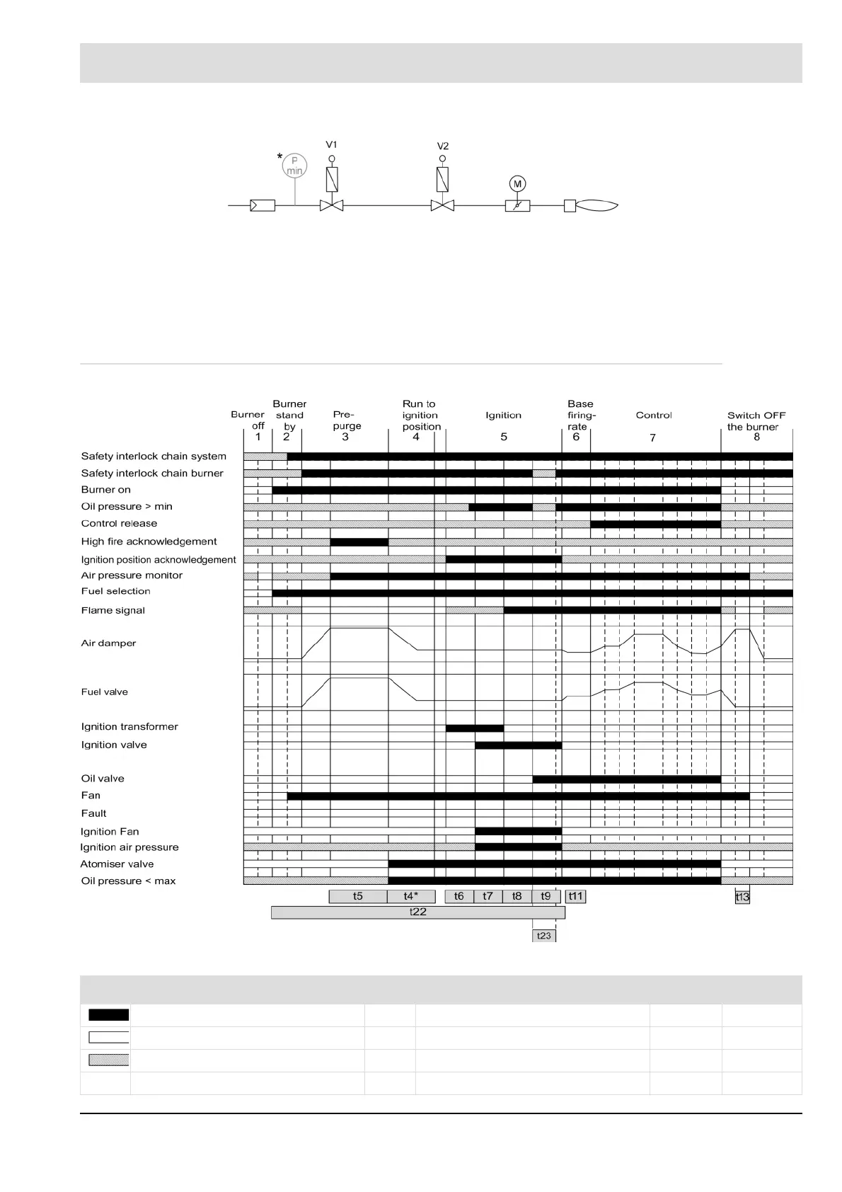
5.1.3 Default Process Flow for Oil Modulating With Pilot Burner
Fig. 5-5 Process sequence chart for oil modulating with pilot burner
V1 Fuel valve on gas side M Actuator drive for gas damper
V2 Fuel valve on burner side P
min
Min. gas pressure monitor
Signal bar Significant times and their parameters Standard
Signal must be present. t4* Parasitic light monitoring time P803 5.0 s
Signal must not be present. t5 Pre-ventilation time P318 1 - 999 s
Signal can be present. t6 Transformer pre-activation time P309 3.0 s
t7 1
st
safety time P305 4.0 s