93
5 Functional Description with Process Diagrams
5.2.4.3 Required Parameters
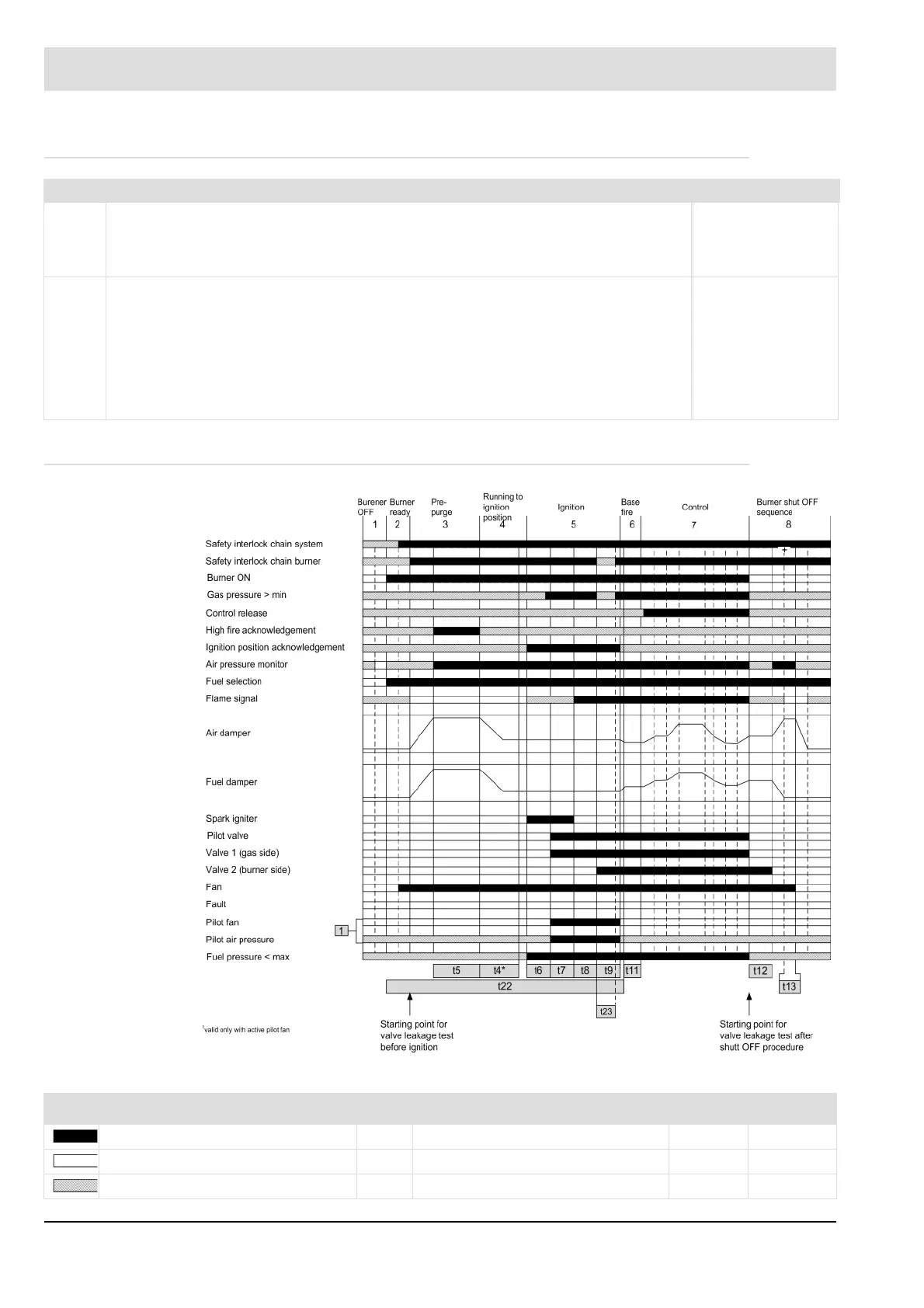
5.2.4.4 Process Sequence Chart: Pilot Burner Continuous Operation
Fig. 5-14 Example: Process sequence chart for gas modulating with pilot burner continuous operation
P no. Description Attributes
302 Control and monitoring of the pilot burner
(0-Start without; 1-Start with; 2-even active in operation; 3-Start with, only pilot flame may be
present during ignition; 4-active in operation, with continuous operation monitoring, only pilot
flame may be present during ignition; 9-Start with, can be switched on during operation)
V1.0.0.0
0 = Start without pilot burner
1 = Start with pilot burner
2 = The pilot burner is active in operation, too.
3 = Start with pilot burner. Only pilot flame may be present during ignition.
4 = Pilot burner is active in operation, with continuous operation monitoring.
Only pilot flame may be present during ignition.
9 = Start with pilot burner.
The pilot burner can be switched on during operation.
Write: 2/GUI/UI
Read: 0
Default: 0
Min: 0
Max: 9
Signal bar Significant times and their parameters Standard
Signal must be present. t4* Parasitic light monitoring time P803 5.0 s
Signal must not be present. t5 Pre-ventilation time P318 1 - 999 s
Signal can be present. t6 Transformer pre-activation time P309 3.0 s