EasyManua.ls Logo

lancer 500 Series - 5. ILLUSTRATIONS, PARTS LISTINGS, AND WIRING DIAGRAMS; 5.1 500 CED WIRING DIAGRAM, 220-240 V;50-60 HZ, LANCER ELECTRONIC ICE BANK CONTROL (INTERNATIONAL ONLY)

lancer 500 Series
16 pages
Print Icon
To Next Page IconTo Next Page
To Previous Page IconTo Previous Page
Loading...
(Section 4.18 continued from previous page)
C. Refrigeration system not C. Refer to Sections 4.11 - 4.15.
running.
D. Refrigerant leak. D. Repair and recharge.
E. Condenser fan motor not E. Replace condenser fan motor.
working.
F. Dirty condenser. F. Clean condenser.
G. Dispenser capacity exceeded. G. Add pre-chiller.
5. ILLUSTRATIONS, PARTS LISTINGS, AND WIRING DIAGRAMS
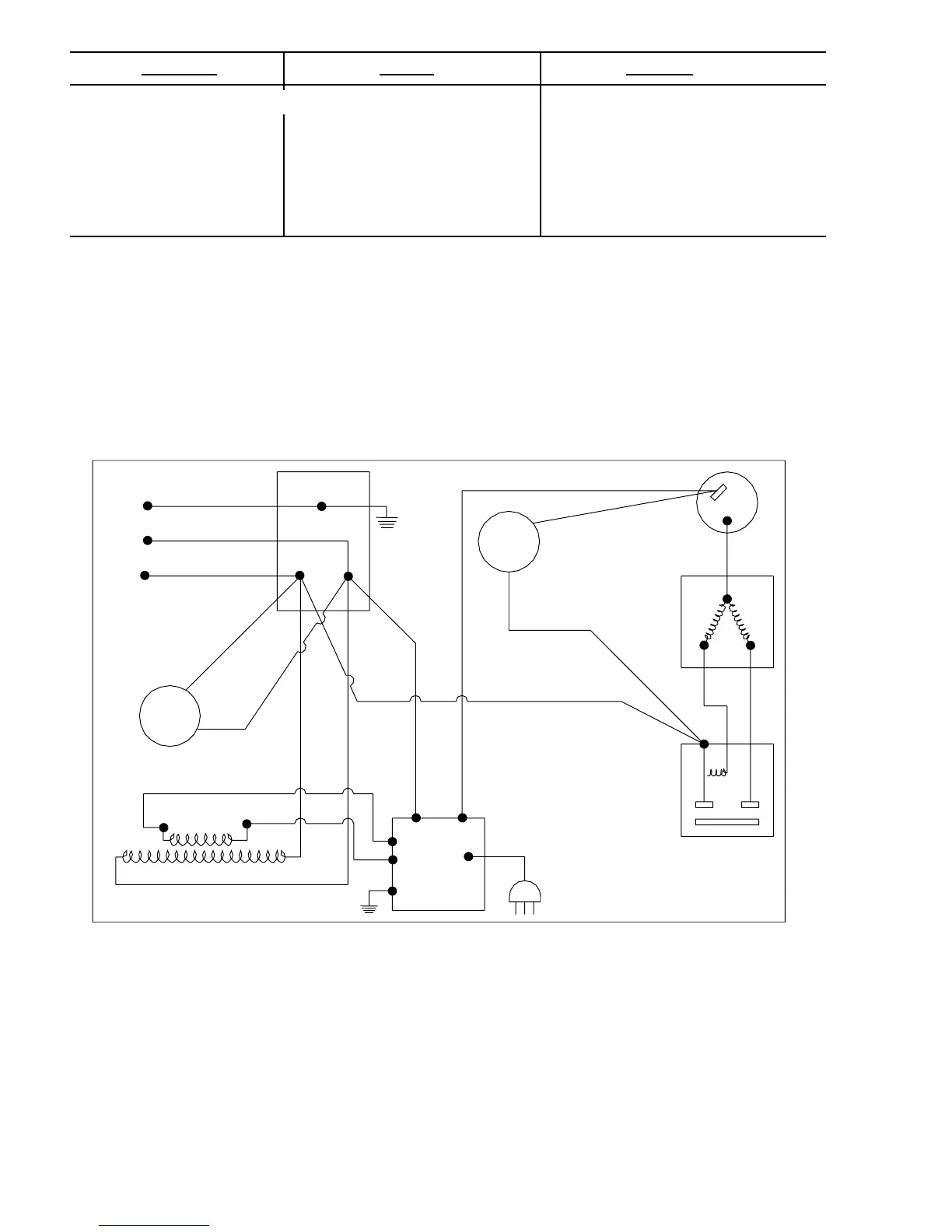
5.1 500 CED WIRING DIAGRAM, 220-240V/50-60HZ,
LANCER ELECTRONIC ICE BANK CONTROL (INTERNATIONAL ONLY)
TROUBLE CAUSE REMEDY
7
WHEN STARTING UNIT OR IF CURRENT IS INTERRUPTED, THERE IS
A FIVE (5) MINUTE DELAY BEFORE THE COMPRESSOR/FAN STARTS.
IMPORTANT
06-2093 USED ON PN 82-2665 (230V/50HZ) AND PN 82-2666 (240V/60HZ)
GREEN
BLACK
WHITE
JCT
220-240V /
50-60HZ AC
FAN
MOTOR
COMPRESSOR
OVERLOAD
C
S
M
M
L
S
RELAY
PROBE
LABEL, WIRING, 500,
REDUNDANT CONTROL
06-2093
LANCER
ICE
BANK
CONTROL
TRANSFORMER
24V LEADS
AGITATOR
MOTOR

Related product manuals