HDK8450 (SM8450P) Processor User Guide Main board
80-28453-2 Rev. C Confidential – Qualcomm Technologies, Inc. and/or its affiliated companies – May Contain Trade Secrets 16
MAY CONTAIN U.S. AND INTERNATIONAL EXPORT CONTROLLED INFORMATION
Enable other boot configuration when
DIP switch turned on. Controlled by
GPIO158.
Default out of the box
configuration is OFF
Enable other boot configuration when
DIP switch turned on. Controlled by
GPIO161.
Default out of the box
configuration is OFF
Enable WATCHDOG_DISABLE
when DIP switch turned on.
Controlled by GPIO164.
Default out of the box
configuration is OFF.
Manually disable external 5V/3.3V
buck output.
Default out of the box
configuration is OFF
Manually disable 1.8V and 3.3V
power suply
Default out of the box
configuration is OFF
Manually connect USB-C headset
detect signal to CODEC
Default is disconnected.
Default out of the box
configuration is OFF.
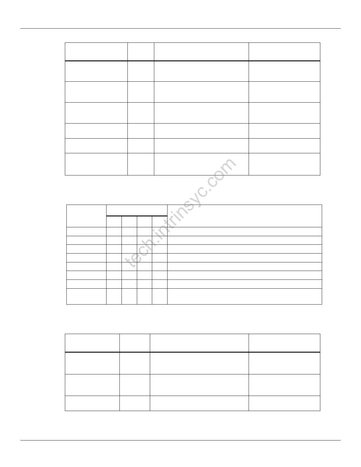
The detailed configuration for boot sequence choice is listed in below table.
Table 3-4 Boot Sequence
Default: UFS0 -> SDC2 -> eDL(USB0)
SDC2 -> UFS0 -> eDL(USB0)
QSPI -> SDC2 -> eDL (USB0)
SPI -> SDC2 -> eDL (USB0)
Same as Fastboot[3:0] = 0000
UFS0 -> SDC2 -> eDL(USB0)
The 8-bit switch of S5702 allows the user to do some general configuration.
Table 3-5 Dip Switch S5702 Configuration
Manually disable external 3.9V buck
output. Default the buck is ON when
DC adapter is plugged in.
Default out of the box
configuration is OFF.
Manually disable battery supply path to
system. Default the path is controlled
by hardware automatically.
Default out of the box
configuration is OFF.
Connect BATT_ID to resistor 1(7.5K).
Default is disconnected.
Default out of the box
configuration is OFF
Confidential -- Lantronix, Inc. Lantronix NDA Requir
ed
 Loading...