HDK8450 (SM8450P) Processor User Guide Main board
80-28453-2 Rev. C Confidential – Qualcomm Technologies, Inc. and/or its affiliated companies – May Contain Trade Secrets 19
MAY CONTAIN U.S. AND INTERNATIONAL EXPORT CONTROLLED INFORMATION
3.4 Main board connectors and features
Table below lists the connectors, expansions and their usages on the main board.
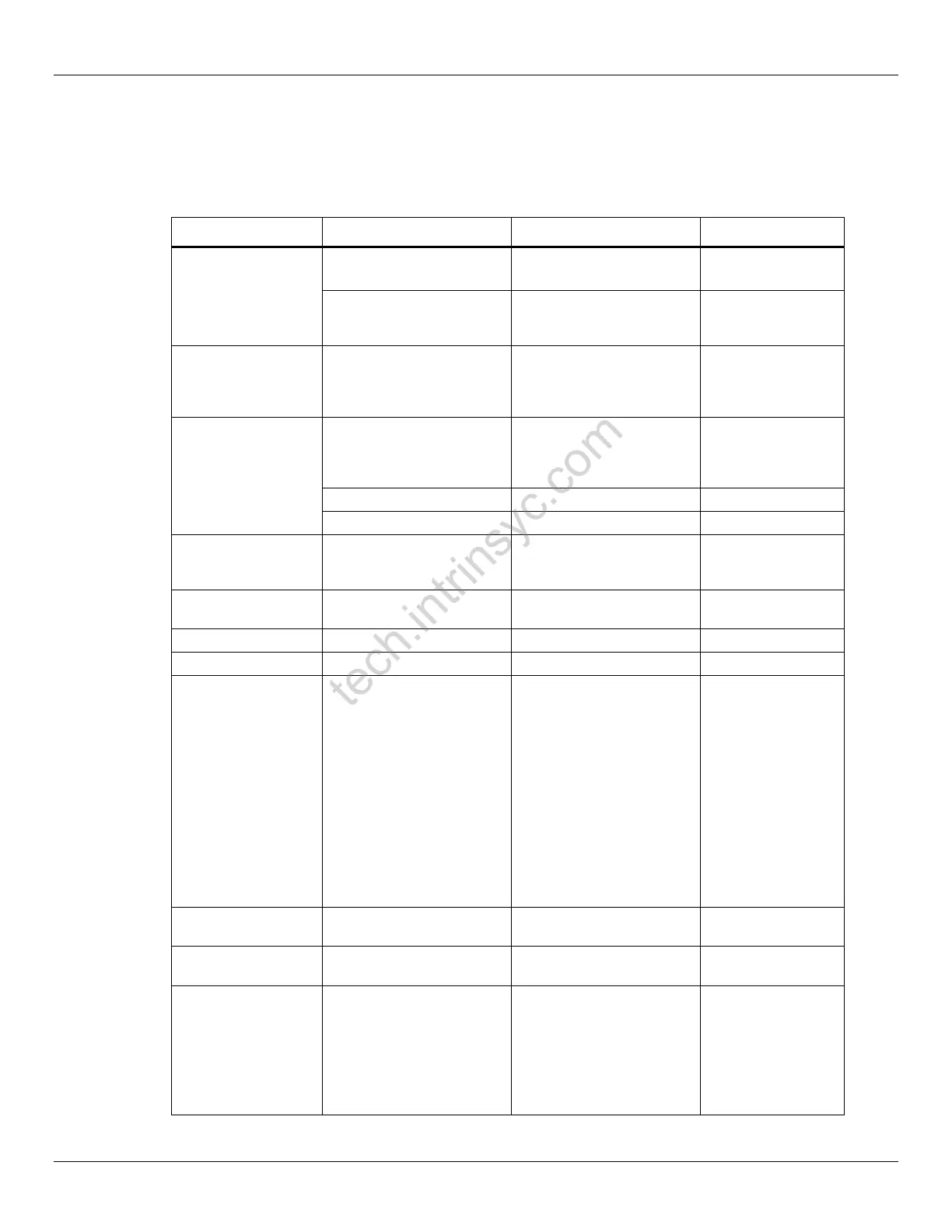
Table 3-6 Main Board Connectors and Features
For providing power
from 4.4V/3780mAh
battery(optional)
Debug Serial UART
console over USB for
development
Development Serial
Connector for
debug output via
USB
Red Power Button
for Suspend /
Resume and Power
off
Normal Open, support US
Standard CTIA headset by
default
Type-C USB3.1 GEN2
10Gbps
1 x 160-pin connector with
MCLK, GPIOS, CCI
Supports CSI0, CSI1, CSI2
and CSI3 via the 160-pin
connector
▪ 4x 4-Lane MIPI-CSI
DPHY1.2 or
▪ 4x 3-Trio MIPI CSI
CPHY1.0
▪ External flash driver
control
▪ Support for 3D camera
configuration
▪ Separate MCLK / CCI
control
▪ Single Rear,
Front camera
▪ Dual Camera
▪ Iris Camera
2x 60 pin-GenX sensor
connector
60-pin GenX sensor
connector
Connector for
sensor card
Connection for
sensor bar
60-pin B2B connector for
DSI0 and CSI4/5 signals.
Compliant with 96boards
HS expansion spec
Supports DSI0 via the 60-
pin connector
▪ 4-Lane MIPI-CSI
DPHY1.2 or
▪ 3-Trio MIPI CSI
CPHY1.1
▪ I2C/SPI/GPIO
FHD 1080x2340
120Hz panel is
supported on
HDK8450
Confidential -- Lantronix, Inc. Lantronix NDA Requir
ed
 Loading...