LT-4100 User & Installation Manual Rev 1.00 DC Isolation Resistance and Chassis Ground
Lars Thrane A/S www.thrane.eu Page 35 of 129
DC Isolation Resistance and Chassis Ground
The LT-4100 system must be installed properly with respect to DC isolation resistance and chassis ground.
Wrong installations can lead to DC isolation issues (low Ohm meter measuring) on board the vessel and
equipment damages. This section will provide details about installation precautions, which must be
followed.
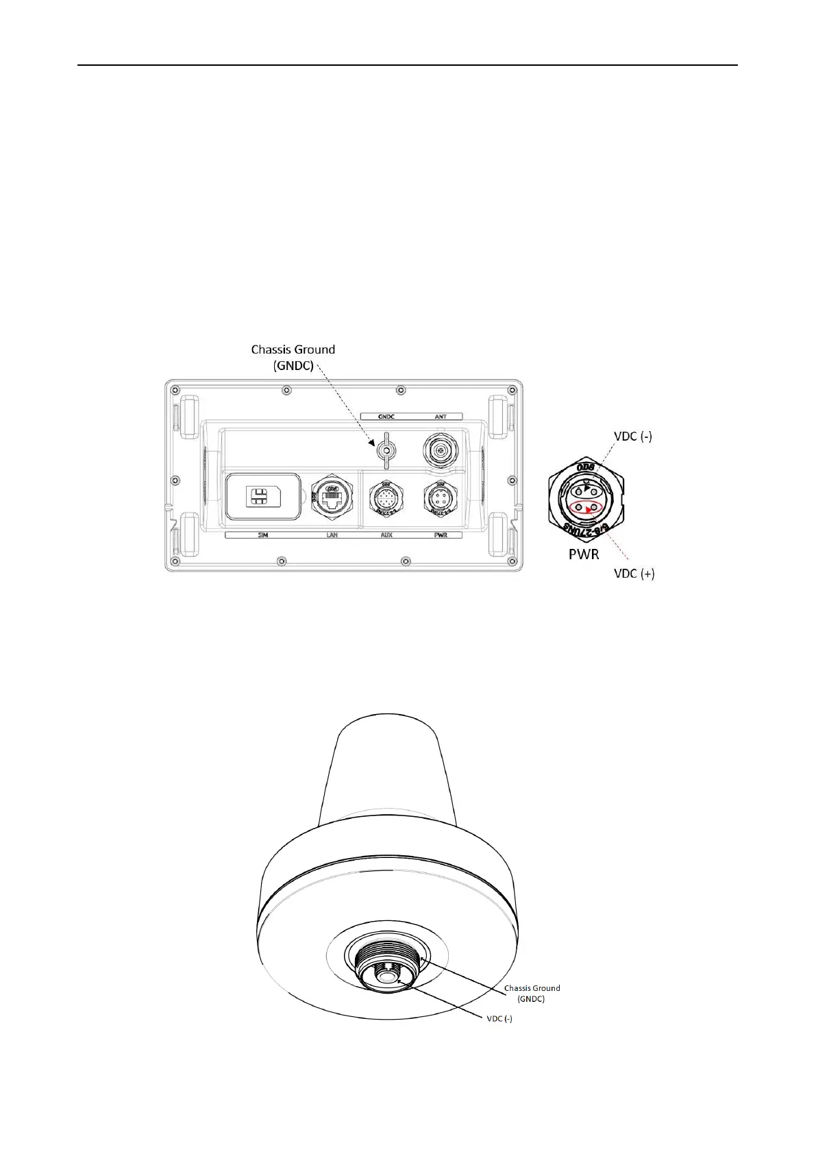
LT-4110 Control Unit (back view) with an upscaled power connector are illustrated in Figure 30. The Chassis
ground (GNDC) must be connected sufficiently to the vessel ground. 91-102218 Power Cable, 3m must be
used to connect the LT-4110 Control Unit to the vessel 12 or 24 VDC power source. DC isolation resistance
measured on a disconnected LT-4110 Control Unit between GNDC and VDC (-) > 50 MΩ.
The LT-4130 Antenna Unit (bottom view) is illustrated in Figure 31. Chassis ground (GNDC) on the LT-4130
Antenna Unit is defined as the mechanics (connected to the mounts).
 Loading...