LT-4100 User & Installation Manual Rev 1.00 DC Isolation Resistance and Chassis Ground
Lars Thrane A/S www.thrane.eu Page 36 of 129
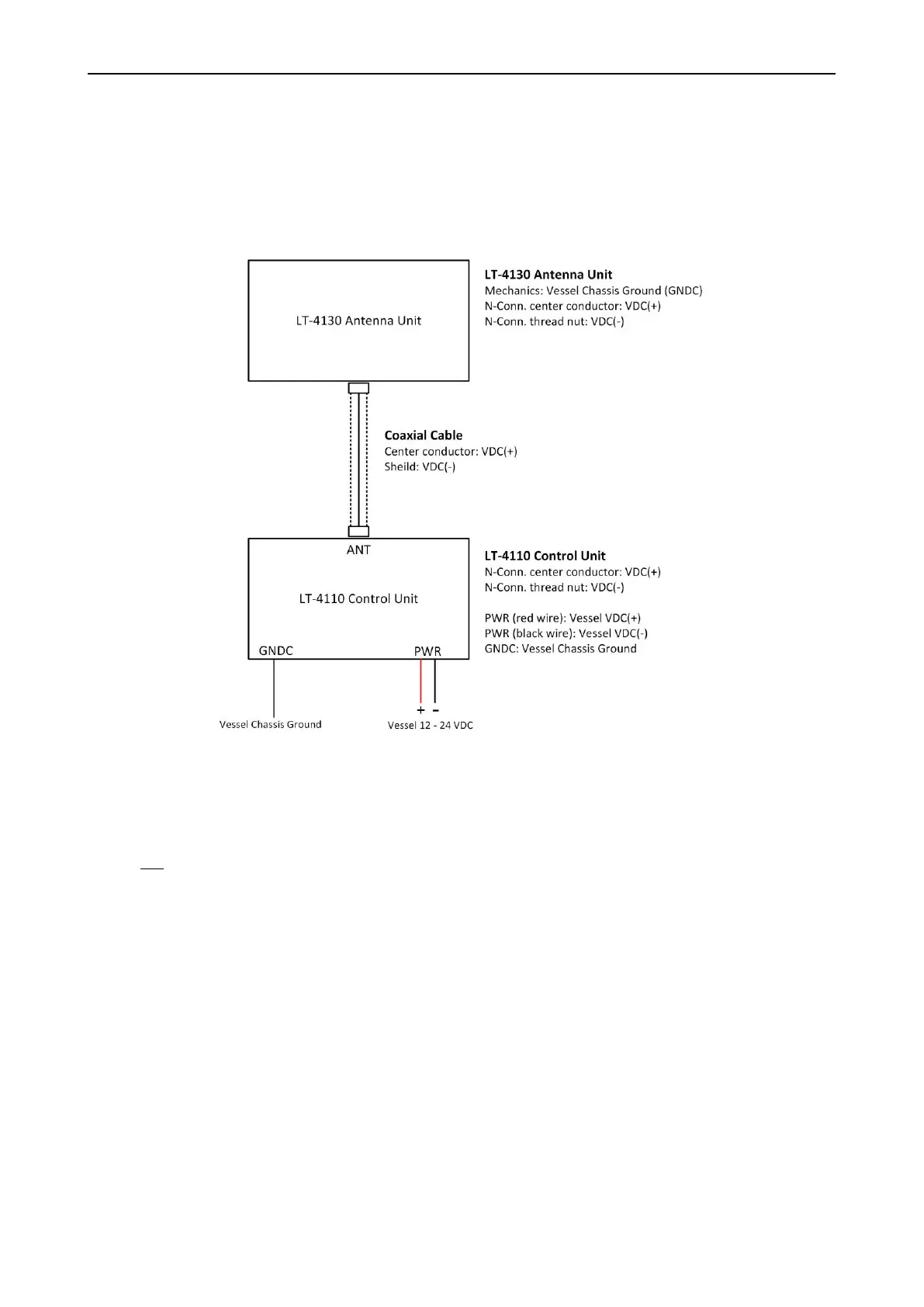
DC isolation resistance measured on a disconnected LT-4130 Antenna Unit between GNDC and VDC (-) > 50
MΩ. VDC (-) and VDC (+) is respectfully the N connector thread and the N connector center conductor.
Figure 32 is illustrating the LT-4100 system consisting of LT-4110 Control Unit, LT-4130 Antenna Unit, and
the coaxial cable connecting these two units.
It is important that the coaxial cable, connected to both the LT-4110 Control Unit and LT-4130 Antenna
Unit, is not grounded in any of the ends. Do not connect the coaxial cable shield to vessel ground. The
coaxial cable N connector must only be connected directly to the N connector of the two units.
NOTE: Make sure that the LT-4130 Antenna Unit is connected sufficiently to vessel ground. Also,
make sure that the N connector on the LT-4130 Antenna Unit, VDC (-) is not connected to
the LT-4130 Antenna Unit mechanics, GNDC. It is important to adhere to this requirement
so as not to get a bad DC isolation resistance.
 Loading...