Section #2 – Speed Measurements 26
Electronic Copy of LTI's UltraLyte LR B User's Manual - 2
nd
Edition © 2002
The cosine effect decreases as the range to the target vehicle increases.
•
At the maximum range of the instrument,
the vehicle is so far
away that the angle between it and the instrument is very
small indeed. The instrument’s perception of the target's speed
is identical to its true speed.
•
As the vehicle approaches,
the angle increases until it becomes
large enough to affect the measurement.
To minimize the cosine effect,
keep the angle small. Set up
the instrument as close to the road as possible without
creating safety risks, and target down the road at ranges
sufficient to keep the angular difference small.
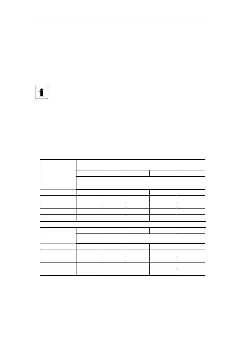
Table 7 shows acceptable parameters for minimizing the cosine effect.
The chart indicates the percentage of true speed measured, given the
distance from the roadway and the distance from the target vehicle.
To find a target's measured speed, multiply the true speed by the
number in the chart.
Table 7. Percentage of True Speed Measured
Range to Target Vehicle
100 ft 250 ft 500 ft 1000 ft 2000 ft
Distance
off the
Roadway
(feet)
fraction of true speed that will be measured
10 .9950 .9992 .9998 .9999 1.0000
25 .9682 .9950 .9987 .9997 .9999
50 .8660 .9798 .9950 .9987 .9997
100 .0000 .9165 .9798 .9950 .9987
200 .0000 .6000 .9165 .9798 .9950
30 m 100 m 150 m 300 m 600 m
(meters)
fraction of true speed that will be measured
3 .9950 .9995 .9998 .9999 1.0000
10 .9682 .9950 .9987 .9997 .9999
15 .8660 .9886 .9950 .9987 .9997
30 .0000 .9539 .9798 .9950 .9987
60 .0000 .7999 .9165 .9798 .9950
The diagonal created by the boldface numbers indicates the boundary
between
acceptable
and
unacceptable
parameters.
•
Numbers above the diagonal
are acceptable margins of error.
•
Numbers below the diagonal
are unacceptable margins of
error.
Remember that the cosine effect is always in the motorist's favor.
 Loading...