Appendix B - Bell Relay Connections • 35
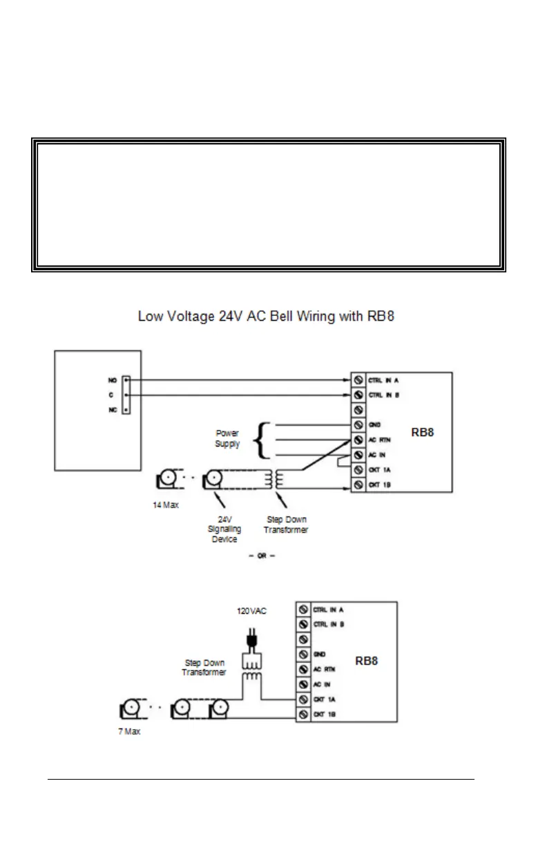
Connect the wires from the signaling device to the screw clocks.
Plug the clock connector into the socket on the PC700. Only one (1)
wire should be inserted into the clock block positions NO and COM,
all wire splices should be done externally. See the following
diagrams for details.
Important! Relay contacts provide no power for signaling devices. The
relay is a dry contact closure rated 2 amps at 24VDC or 120 VAC.
Connecting a device or series of devices that draw more than the rated
amperage from the clock will result in serious damage! It is
recommended to use the optional RB8 Relay Booster Box to control
devices that require more than 2 amps.